

3.4 Solved Problems
61
node 5: 0 + u 3 − 4u 4 + 6u 5 − 4u 6 = 0 ,
(3.105)
node 6: 0 + 0 + u 4 − 4u 5 + 5u 5 = 0 ,
(3.106)
or in matrix notation as:
⎡
⎢
⎢
⎢
⎢
⎣
5 −4 1 0 0
−4 6 −4 1 0
1 −4 6 −4 1
0 1 −4 6 −4
0 0 1 −4 6
⎤
⎥
⎥
⎥
⎥
⎦
⎡
⎢
⎢
⎢
⎢
⎣
u 2
u 3
u 4
u 5
u 6
⎤
⎥
⎥
⎥
⎥
⎦
= −
X
3 F 0
E I Y
⎡
⎢
⎢
⎢
⎢
⎣
0
0
1
0
0
⎤
⎥
⎥
⎥
⎥
⎦
.
(3.107)
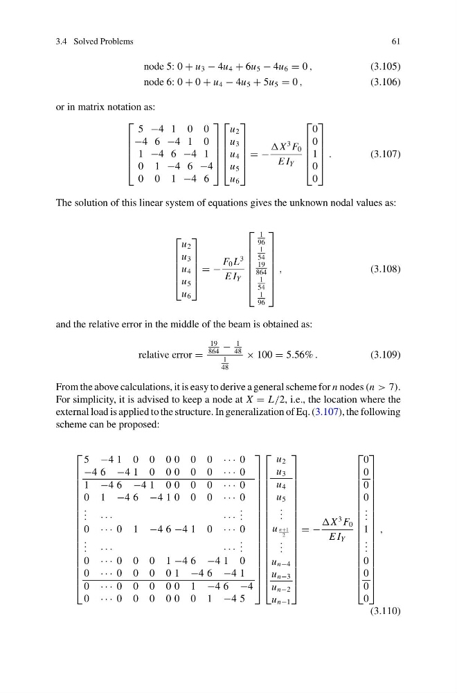
The solution of this linear system of equations gives the unknown nodal values as:
⎡
⎢
⎢
⎢
⎢
⎣
u 2
u 3
u 4
u 5
u 6
⎤
⎥
⎥
⎥
⎥
⎦
= −
F 0 L
3
E I Y
⎡
⎢
⎢
⎢
⎢
⎢
⎢
⎣
1
96
1
54
19
864
1
54
1
96
⎤
⎥
⎥
⎥
⎥
⎥
⎥
⎦
,
(3.108)
and the relative error in the middle of the beam is obtained as:
relative error =
19
864
−
1
48
1
48
× 100 = 5.56% .
(3.109)
From the above calculations, it is easy to derive a general scheme for n nodes (n > 7).
For simplicity, it is advised to keep a node at X = L/2, i.e., the location where the
external load is applied to the structure. In generalization of Eq. (3.107), the following
scheme can be proposed:
⎡
⎢
⎢
⎢
⎢
⎢
⎢
⎢
⎢
⎢
⎢
⎢
⎢
⎢
⎢
⎢
⎢
⎢
⎢
⎣
5 −4 1 0 0 0 0 0 0 · · · 0
−4 6 −4 1 0 0 0 0 0 · · · 0
1 −4 6 −4 1 0 0 0 0 · · · 0
0 1 −4 6 −4 1 0 0 0 · · · 0
. . . · · ·
· · ·
. . .
0 · · · 0 1 −4 6 −4 1 0 · · · 0
. . . · · ·
· · ·
. . .
0 · · · 0 0 0 1 −4 6 −4 1 0
0 · · · 0 0 0 0 1 −4 6 −4 1
0 · · · 0 0 0 0 0 1 −4 6 −4
0 · · · 0 0 0 0 0 0 1 −4 5
⎤
⎥
⎥
⎥
⎥
⎥
⎥
⎥
⎥
⎥
⎥
⎥
⎥
⎥
⎥
⎥
⎥
⎥
⎥
⎦
⎡
⎢
⎢
⎢
⎢
⎢
⎢
⎢
⎢
⎢
⎢
⎢
⎢
⎢
⎢
⎢
⎢
⎢
⎢
⎣
u 2
u 3
u 4
u 5
. . .
u n+1
2
. . .
u n−4
u n−3
u n−2
u n−1
⎤
⎥
⎥
⎥
⎥
⎥
⎥
⎥
⎥
⎥
⎥
⎥
⎥
⎥
⎥
⎥
⎥
⎥
⎥
⎦
= −
X
3 F 0
E I Y
⎡
⎢
⎢
⎢
⎢
⎢
⎢
⎢
⎢
⎢
⎢
⎢
⎢
⎢
⎢
⎢
⎢
⎢
⎢
⎣
0
0
0
0
. . .
1
. . .
0
0
0
0
⎤
⎥
⎥
⎥
⎥
⎥
⎥
⎥
⎥
⎥
⎥
⎥
⎥
⎥
⎥
⎥
⎥
⎥
⎥
⎦
,
(3.110)
61
node 5: 0 + u 3 − 4u 4 + 6u 5 − 4u 6 = 0 ,
(3.105)
node 6: 0 + 0 + u 4 − 4u 5 + 5u 5 = 0 ,
(3.106)
or in matrix notation as:
⎡
⎢
⎢
⎢
⎢
⎣
5 −4 1 0 0
−4 6 −4 1 0
1 −4 6 −4 1
0 1 −4 6 −4
0 0 1 −4 6
⎤
⎥
⎥
⎥
⎥
⎦
⎡
⎢
⎢
⎢
⎢
⎣
u 2
u 3
u 4
u 5
u 6
⎤
⎥
⎥
⎥
⎥
⎦
= −
X
3 F 0
E I Y
⎡
⎢
⎢
⎢
⎢
⎣
0
0
1
0
0
⎤
⎥
⎥
⎥
⎥
⎦
.
(3.107)
The solution of this linear system of equations gives the unknown nodal values as:
⎡
⎢
⎢
⎢
⎢
⎣
u 2
u 3
u 4
u 5
u 6
⎤
⎥
⎥
⎥
⎥
⎦
= −
F 0 L
3
E I Y
⎡
⎢
⎢
⎢
⎢
⎢
⎢
⎣
1
96
1
54
19
864
1
54
1
96
⎤
⎥
⎥
⎥
⎥
⎥
⎥
⎦
,
(3.108)
and the relative error in the middle of the beam is obtained as:
relative error =
19
864
−
1
48
1
48
× 100 = 5.56% .
(3.109)
From the above calculations, it is easy to derive a general scheme for n nodes (n > 7).
For simplicity, it is advised to keep a node at X = L/2, i.e., the location where the
external load is applied to the structure. In generalization of Eq. (3.107), the following
scheme can be proposed:
⎡
⎢
⎢
⎢
⎢
⎢
⎢
⎢
⎢
⎢
⎢
⎢
⎢
⎢
⎢
⎢
⎢
⎢
⎢
⎣
5 −4 1 0 0 0 0 0 0 · · · 0
−4 6 −4 1 0 0 0 0 0 · · · 0
1 −4 6 −4 1 0 0 0 0 · · · 0
0 1 −4 6 −4 1 0 0 0 · · · 0
. . . · · ·
· · ·
. . .
0 · · · 0 1 −4 6 −4 1 0 · · · 0
. . . · · ·
· · ·
. . .
0 · · · 0 0 0 1 −4 6 −4 1 0
0 · · · 0 0 0 0 1 −4 6 −4 1
0 · · · 0 0 0 0 0 1 −4 6 −4
0 · · · 0 0 0 0 0 0 1 −4 5
⎤
⎥
⎥
⎥
⎥
⎥
⎥
⎥
⎥
⎥
⎥
⎥
⎥
⎥
⎥
⎥
⎥
⎥
⎥
⎦
⎡
⎢
⎢
⎢
⎢
⎢
⎢
⎢
⎢
⎢
⎢
⎢
⎢
⎢
⎢
⎢
⎢
⎢
⎢
⎣
u 2
u 3
u 4
u 5
. . .
u n+1
2
. . .
u n−4
u n−3
u n−2
u n−1
⎤
⎥
⎥
⎥
⎥
⎥
⎥
⎥
⎥
⎥
⎥
⎥
⎥
⎥
⎥
⎥
⎥
⎥
⎥
⎦
= −
X
3 F 0
E I Y
⎡
⎢
⎢
⎢
⎢
⎢
⎢
⎢
⎢
⎢
⎢
⎢
⎢
⎢
⎢
⎢
⎢
⎢
⎢
⎣
0
0
0
0
. . .
1
. . .
0
0
0
0
⎤
⎥
⎥
⎥
⎥
⎥
⎥
⎥
⎥
⎥
⎥
⎥
⎥
⎥
⎥
⎥
⎥
⎥
⎥
⎦
,
(3.110)