

3.4 Solved Problems
53
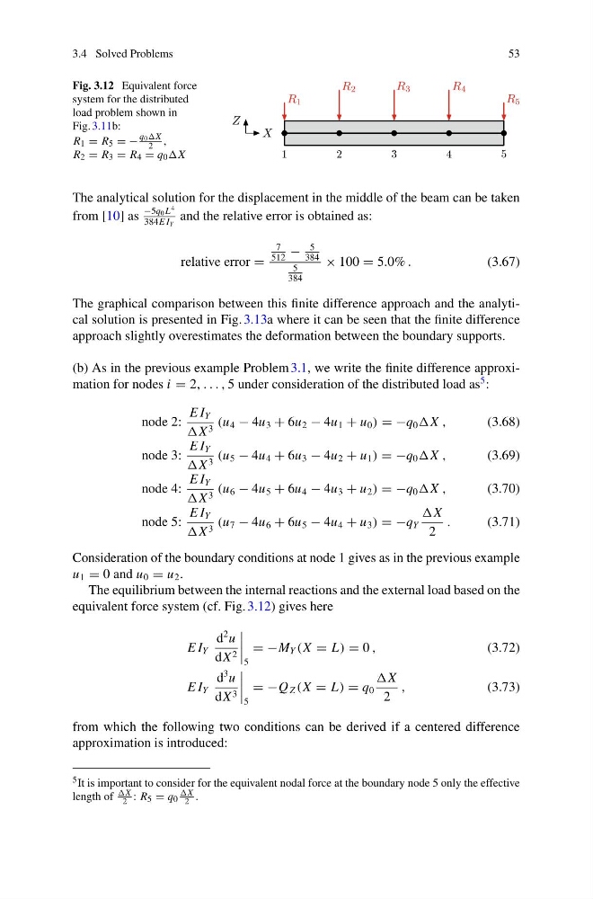
Fig. 3.12 Equivalent force
system for the distributed
load problem shown in
Fig. 3.11b:
R 1 = R 5 = −
q0X
2 ,
R 2 = R 3 = R 4 = q 0
The analytical solution for the displacement in the middle of the beam can be taken
from [10] as
−5q 0 L
4
384E I Y
and the relative error is obtained as:
relative error =
7
512
−
5
384
5
384
× 100 = 5.0% .
(3.67)
The graphical comparison between this finite difference approach and the analytical solution is presented in Fig. 3.13a where it can be seen that the finite difference
approach slightly overestimates the deformation between the boundary supports.
(b) As in the previous example Problem 3.1, we write the finite difference approximation for nodes i = 2, . . . , 5 under consideration of the distributed load as
5 :
node 2:
E I Y
X 3 (u 4 − 4u 3 + 6u 2 − 4u 1 + u 0 ) = −q 0 ,
(3.68)
node 3:
E I Y
X 3 (u 5 − 4u 4 + 6u 3 − 4u 2 + u 1 ) = −q 0 ,
(3.69)
node 4:
E I Y
X 3 (u 6 − 4u 5 + 6u 4 − 4u 3 + u 2 ) = −q 0 ,
(3.70)
node 5:
E I Y
X 3 (u 7 − 4u 6 + 6u 5 − 4u 4 + u 3 ) = −q Y
2
.
(3.71)
Consideration of the boundary conditions at node 1 gives as in the previous example
u 1 = 0 and u 0 = u 2 .
The equilibrium between the internal reactions and the external load based on the
equivalent force system (cf. Fig. 3.12) gives here
E I Y
d
2 u
dX 2
5
= −M Y (X = L) = 0 ,
(3.72)
E I Y
d
3 u
dX 3
5
= −Q Z (X = L) = q 0
2
,
(3.73)
from which the following two conditions can be derived if a centered difference
approximation is introduced:
5 It is important to consider for the equivalent nodal force at the boundary node 5 only the effective
length of
2 : R 5 = q 0
2 .
53
Fig. 3.12 Equivalent force
system for the distributed
load problem shown in
Fig. 3.11b:
R 1 = R 5 = −
q0X
2 ,
R 2 = R 3 = R 4 = q 0
The analytical solution for the displacement in the middle of the beam can be taken
from [10] as
−5q 0 L
4
384E I Y
and the relative error is obtained as:
relative error =
7
512
−
5
384
5
384
× 100 = 5.0% .
(3.67)
The graphical comparison between this finite difference approach and the analytical solution is presented in Fig. 3.13a where it can be seen that the finite difference
approach slightly overestimates the deformation between the boundary supports.
(b) As in the previous example Problem 3.1, we write the finite difference approximation for nodes i = 2, . . . , 5 under consideration of the distributed load as
5 :
node 2:
E I Y
X 3 (u 4 − 4u 3 + 6u 2 − 4u 1 + u 0 ) = −q 0 ,
(3.68)
node 3:
E I Y
X 3 (u 5 − 4u 4 + 6u 3 − 4u 2 + u 1 ) = −q 0 ,
(3.69)
node 4:
E I Y
X 3 (u 6 − 4u 5 + 6u 4 − 4u 3 + u 2 ) = −q 0 ,
(3.70)
node 5:
E I Y
X 3 (u 7 − 4u 6 + 6u 5 − 4u 4 + u 3 ) = −q Y
2
.
(3.71)
Consideration of the boundary conditions at node 1 gives as in the previous example
u 1 = 0 and u 0 = u 2 .
The equilibrium between the internal reactions and the external load based on the
equivalent force system (cf. Fig. 3.12) gives here
E I Y
d
2 u
dX 2
5
= −M Y (X = L) = 0 ,
(3.72)
E I Y
d
3 u
dX 3
5
= −Q Z (X = L) = q 0
2
,
(3.73)
from which the following two conditions can be derived if a centered difference
approximation is introduced:
5 It is important to consider for the equivalent nodal force at the boundary node 5 only the effective
length of
2 : R 5 = q 0
2 .