

112
5 Consideration of Euler–Bernoulli Beams with Plastic Material Behavior
5.2 Supplementary Problems
5.1 Comparison between analytical and layer-wise integration of the bending
stiffness
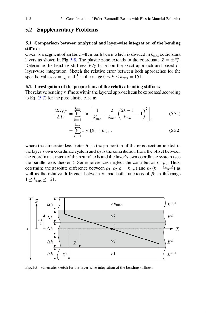
Given is a segment of an Euler–Bernoulli beam which is divided in k max equidistant
layers as shown in Fig. 5.8. The plastic zone extends to the coordinate Z = ±
αh
2
.
Determine the bending stiffness E I Y based on the exact approach and based on
layer-wise integration. Sketch the relative error between both approaches for the
specific values α =
11
20
and
1
2
in the range 0 ≤ k ≤ k max = 151.
5.2 Investigation of the proportions of the relative bending stiffness
The relative bending stiffness within the layered approach can be expressed according
to Eq. (5.7) for the pure elastic case as
(E I Y ) i
E I Y
=
k max
k = 1
1 ×
1
k 3
max
+
3
k max
2k − 1
k max
− 1
2
i
(5.31)
=
k max
k = 1
1 × [β 1 + β 2 ] i ,
(5.32)
where the dimensionless factor β 1 is the proportion of the cross section related to
the layer’s own coordinate system and β 2 is the contribution from the offset between
the coordinate system of the neutral axis and the layer’s own coordinate system (see
the parallel axis theorem). Some references neglect the contribution of β 1 . Thus,
determine the absolute difference between β 1 , β 2 (k = k max ) and β 2
k =
k max +3
2
as
well as the relative difference between β 1 and both functions of β 2 in the range
1 ≤ k max ≤ 151.
Fig. 5.8 Schematic sketch for the layer-wise integration of the bending stiffness
5 Consideration of Euler–Bernoulli Beams with Plastic Material Behavior
5.2 Supplementary Problems
5.1 Comparison between analytical and layer-wise integration of the bending
stiffness
Given is a segment of an Euler–Bernoulli beam which is divided in k max equidistant
layers as shown in Fig. 5.8. The plastic zone extends to the coordinate Z = ±
αh
2
.
Determine the bending stiffness E I Y based on the exact approach and based on
layer-wise integration. Sketch the relative error between both approaches for the
specific values α =
11
20
and
1
2
in the range 0 ≤ k ≤ k max = 151.
5.2 Investigation of the proportions of the relative bending stiffness
The relative bending stiffness within the layered approach can be expressed according
to Eq. (5.7) for the pure elastic case as
(E I Y ) i
E I Y
=
k max
k = 1
1 ×
1
k 3
max
+
3
k max
2k − 1
k max
− 1
2
i
(5.31)
=
k max
k = 1
1 × [β 1 + β 2 ] i ,
(5.32)
where the dimensionless factor β 1 is the proportion of the cross section related to
the layer’s own coordinate system and β 2 is the contribution from the offset between
the coordinate system of the neutral axis and the layer’s own coordinate system (see
the parallel axis theorem). Some references neglect the contribution of β 1 . Thus,
determine the absolute difference between β 1 , β 2 (k = k max ) and β 2
k =
k max +3
2
as
well as the relative difference between β 1 and both functions of β 2 in the range
1 ≤ k max ≤ 151.
Fig. 5.8 Schematic sketch for the layer-wise integration of the bending stiffness