

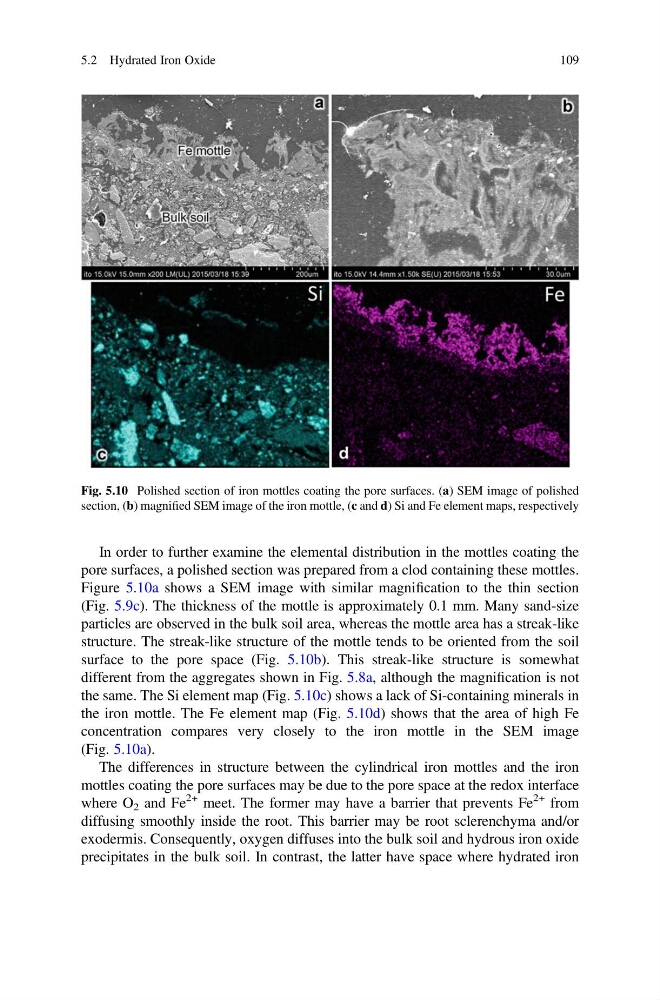
In order to further examine the elemental distribution in the mottles coating the
pore surfaces, a polished section was prepared from a clod containing these mottles.
Figure 5.10a shows a SEM image with similar magnification to the thin section
(Fig. 5.9c). The thickness of the mottle is approximately 0.1 mm. Many sand-size
particles are observed in the bulk soil area, whereas the mottle area has a streak-like
structure. The streak-like structure of the mottle tends to be oriented from the soil
surface to the pore space (Fig. 5.10b). This streak-like structure is somewhat
different from the aggregates shown in Fig. 5.8a, although the magnification is not
the same. The Si element map (Fig. 5.10c) shows a lack of Si-containing minerals in
the iron mottle. The Fe element map (Fig. 5.10d) shows that the area of high Fe
concentration compares very closely to the iron mottle in the SEM image
(Fig. 5.10a).
The differences in structure between the cylindrical iron mottles and the iron
mottles coating the pore surfaces may be due to the pore space at the redox interface
where O 2 and Fe
2+ meet. The former may have a barrier that prevents Fe
2+ from
diffusing smoothly inside the root. This barrier may be root sclerenchyma and/or
exodermis. Consequently, oxygen diffuses into the bulk soil and hydrous iron oxide
precipitates in the bulk soil. In contrast, the latter have space where hydrated iron
Fig. 5.10 Polished section of iron mottles coating the pore surfaces. (a) SEM image of polished
section, (b) magnified SEM image of the iron mottle, (c and d) Si and Fe element maps, respectively
5.2 Hydrated Iron Oxide
109
pore surfaces, a polished section was prepared from a clod containing these mottles.
Figure 5.10a shows a SEM image with similar magnification to the thin section
(Fig. 5.9c). The thickness of the mottle is approximately 0.1 mm. Many sand-size
particles are observed in the bulk soil area, whereas the mottle area has a streak-like
structure. The streak-like structure of the mottle tends to be oriented from the soil
surface to the pore space (Fig. 5.10b). This streak-like structure is somewhat
different from the aggregates shown in Fig. 5.8a, although the magnification is not
the same. The Si element map (Fig. 5.10c) shows a lack of Si-containing minerals in
the iron mottle. The Fe element map (Fig. 5.10d) shows that the area of high Fe
concentration compares very closely to the iron mottle in the SEM image
(Fig. 5.10a).
The differences in structure between the cylindrical iron mottles and the iron
mottles coating the pore surfaces may be due to the pore space at the redox interface
where O 2 and Fe
2+ meet. The former may have a barrier that prevents Fe
2+ from
diffusing smoothly inside the root. This barrier may be root sclerenchyma and/or
exodermis. Consequently, oxygen diffuses into the bulk soil and hydrous iron oxide
precipitates in the bulk soil. In contrast, the latter have space where hydrated iron
Fig. 5.10 Polished section of iron mottles coating the pore surfaces. (a) SEM image of polished
section, (b) magnified SEM image of the iron mottle, (c and d) Si and Fe element maps, respectively
5.2 Hydrated Iron Oxide
109