

Safety of 5G Network Physical Infrastructures 177
overall (drag) force coefficients, which account for group and shielding effects. They
should not be applied to the area of a single element. but directly to the area equal to the
sum of the area of the elements of the most unfavourable exposed face (reference face),
projected normal to the face.
The force coefficients provided in Sections 7.6 to 7.11 of BS EN 1991‐1‐4 correspond
to infinitely long bodies (represented with symbol c f,0 ). To account for the reduced wind
effects caused by wind flows around the ends of a finite body, the code multiplies the
force coefficients by an end‐effect factor, ψλ, which depends on the body slenderness, λ,
and solidity ratio, φ. Care should be paid when determining the value of the end‐effect
factor: for the force coefficients provided in Sections 7.6 to 7.10, the slenderness and
relative position should be determined for the single element, whereas for Section 7.11,
the corresponding values should be determined for the reference face [35].
When there are elements with different shapes in a single face, the overall force coefficient could be determined by a weighted average:
c c
A
A
c
A
A
c
A
A
f
fc
c
face
f c
c
face
f a
a
face
,
, ,sup
,sup
,
(8.7)
where A c and c f,c represent the exposed area and force coefficient of the elements with
circular shape in sub‐critical flow regimes, respectively; A c,sup and c f,c,sup represent the
exposed area and force coefficient of the elements with circular shape in supercritical
flow regimes, respectively; A a and c f,a represent the exposed area and force coefficient of
the elements with angular shape, respectively.
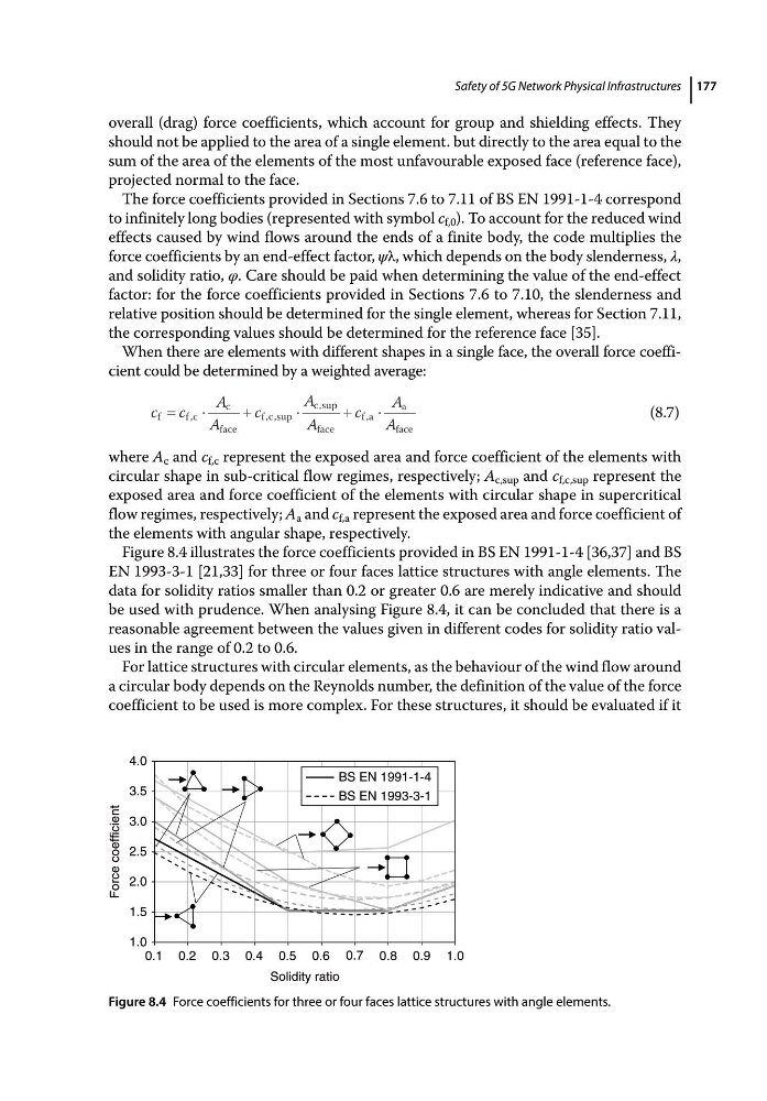
Figure 8.4 illustrates the force coefficients provided in BS EN 1991‐1‐4 [36,37] and BS
EN 1993‐3‐1 [21,33] for three or four faces lattice structures with angle elements. The
data for solidity ratios smaller than 0.2 or greater 0.6 are merely indicative and should
be used with prudence. When analysing Figure 8.4, it can be concluded that there is a
reasonable agreement between the values given in different codes for solidity ratio values in the range of 0.2 to 0.6.
For lattice structures with circular elements, as the behaviour of the wind flow around
a circular body depends on the Reynolds number, the definition of the value of the force
coefficient to be used is more complex. For these structures, it should be evaluated if it
1.0
1.5
2.0
2.5
3.0
3.5
4.0
0.1 0.2 0.3 0.4 0.5 0.6 0.7 0.8 0.9 1.0
Force coefficient
Solidity ratio
BS EN 1991-1-4
BS EN 1993-3-1
Figure 8.4 Force coefficients for three or four faces lattice structures with angle elements.
overall (drag) force coefficients, which account for group and shielding effects. They
should not be applied to the area of a single element. but directly to the area equal to the
sum of the area of the elements of the most unfavourable exposed face (reference face),
projected normal to the face.
The force coefficients provided in Sections 7.6 to 7.11 of BS EN 1991‐1‐4 correspond
to infinitely long bodies (represented with symbol c f,0 ). To account for the reduced wind
effects caused by wind flows around the ends of a finite body, the code multiplies the
force coefficients by an end‐effect factor, ψλ, which depends on the body slenderness, λ,
and solidity ratio, φ. Care should be paid when determining the value of the end‐effect
factor: for the force coefficients provided in Sections 7.6 to 7.10, the slenderness and
relative position should be determined for the single element, whereas for Section 7.11,
the corresponding values should be determined for the reference face [35].
When there are elements with different shapes in a single face, the overall force coefficient could be determined by a weighted average:
c c
A
A
c
A
A
c
A
A
f
fc
c
face
f c
c
face
f a
a
face
,
, ,sup
,sup
,
(8.7)
where A c and c f,c represent the exposed area and force coefficient of the elements with
circular shape in sub‐critical flow regimes, respectively; A c,sup and c f,c,sup represent the
exposed area and force coefficient of the elements with circular shape in supercritical
flow regimes, respectively; A a and c f,a represent the exposed area and force coefficient of
the elements with angular shape, respectively.
Figure 8.4 illustrates the force coefficients provided in BS EN 1991‐1‐4 [36,37] and BS
EN 1993‐3‐1 [21,33] for three or four faces lattice structures with angle elements. The
data for solidity ratios smaller than 0.2 or greater 0.6 are merely indicative and should
be used with prudence. When analysing Figure 8.4, it can be concluded that there is a
reasonable agreement between the values given in different codes for solidity ratio values in the range of 0.2 to 0.6.
For lattice structures with circular elements, as the behaviour of the wind flow around
a circular body depends on the Reynolds number, the definition of the value of the force
coefficient to be used is more complex. For these structures, it should be evaluated if it
1.0
1.5
2.0
2.5
3.0
3.5
4.0
0.1 0.2 0.3 0.4 0.5 0.6 0.7 0.8 0.9 1.0
Force coefficient
Solidity ratio
BS EN 1991-1-4
BS EN 1993-3-1
Figure 8.4 Force coefficients for three or four faces lattice structures with angle elements.