

Travanca and André
176
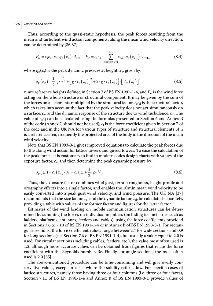
Thus, according to the quasi‐static hypothesis, the peak forces resulting from the
mean and turbulent wind action components, along the mean wind velocity direction,
can be determined by [36,37]:
F
c c c q z A
F
c c
c q z
j
j n
j
j
w
s d f
p
e
ref
w
s d
element
f
p
e
,
,
,
1
A j
ref ,
(8.4)
where q p (z e ) is the peak dynamic pressure at height, z e , given by:
q z
g I z
g I z
V z
e
e
e
e
p
v
v
m
1
2
1
2
2
2
(8.5)
z e are reference heights defined in Section 7 of BS EN 1991‐1‐4, and F w is the wind force
acting on the whole structure or structural component. It may be given by the sum of
the forces on all elements multiplied by the structural factor. c s c d is the structural factor,
which takes into account the fact that the peak velocity does not act simultaneously on
a surface, c s , and the dynamic response of the structure due to wind turbulence, c d . The
value of c s c d can be calculated using the formulas presented in Section 6 and Annex B
of the code (Annex C should not be used); c f is the force coefficient given in Section 7 of
the code and in the UK NA for various types of structure and structural elements; A ref
is a reference area, frequently the projected area of the body in the direction of the mean
wind velocity.
Note that BS EN 1993‐3‐1 gives improved equations to calculate the peak forces due
to the along wind action for lattice towers and guyed towers. To ease the calculation of
the peak forces, it is customary to find in modern codes design charts with values of the
exposure factor, c e , and then determine the peak dynamic pressure by:
q z
c z q c z
V
e
e
e
p
e
b
e
b
1
2
(8.6)
Thus, the exposure factor combines wind gust, terrain roughness, height profile and
orography effects into a single factor, and enables the 10 min mean wind velocity to be
easily converted into a peak gust wind velocity, and wind pressure. The UK NA [37]
recommends that the size factor, c s , and the dynamic factor, c d , be calculated separately,
providing a table with values of the former factor and figures for the latter factor.
Estimates of the wind loading on mobile communication structures can be determined by summing the forces on individual members (including its ancillaries such as
ladders, platforms, antennas, feeders and cables), using the force coefficients provided
in Sections 7.6 to 7.10 of BS EN 1991‐1‐4 or in Annex B of BS EN 1993‐3‐1. For rectangular sections, the force coefficient values range between 2.4 for wide sections and 0.9
for long sections (see Section 7.6 of BS EN 1991‐1‐4), but usually a value equal to 2.0 is
used. For circular sections (including cables, feeders, etc.), the value most often used is
1.2, although more accurate values can be obtained from figures that relate the force
coefficient with the Reynolds number, Re. Finally, for angle sections, the most often
used is 2.0 [35].
The above‐mentioned procedure can be time‐consuming and will give overly conservative values, except in cases where the solidity ratio is low. For specific cases of
lattice structures, namely those having three or four columns (i.e. three or four faces),
Section 7.11 of BS EN 1991‐1‐4 and Annex B of BS EN 1993‐3‐1 provide values of
176
Thus, according to the quasi‐static hypothesis, the peak forces resulting from the
mean and turbulent wind action components, along the mean wind velocity direction,
can be determined by [36,37]:
F
c c c q z A
F
c c
c q z
j
j n
j
j
w
s d f
p
e
ref
w
s d
element
f
p
e
,
,
,
1
A j
ref ,
(8.4)
where q p (z e ) is the peak dynamic pressure at height, z e , given by:
q z
g I z
g I z
V z
e
e
e
e
p
v
v
m
1
2
1
2
2
2
(8.5)
z e are reference heights defined in Section 7 of BS EN 1991‐1‐4, and F w is the wind force
acting on the whole structure or structural component. It may be given by the sum of
the forces on all elements multiplied by the structural factor. c s c d is the structural factor,
which takes into account the fact that the peak velocity does not act simultaneously on
a surface, c s , and the dynamic response of the structure due to wind turbulence, c d . The
value of c s c d can be calculated using the formulas presented in Section 6 and Annex B
of the code (Annex C should not be used); c f is the force coefficient given in Section 7 of
the code and in the UK NA for various types of structure and structural elements; A ref
is a reference area, frequently the projected area of the body in the direction of the mean
wind velocity.
Note that BS EN 1993‐3‐1 gives improved equations to calculate the peak forces due
to the along wind action for lattice towers and guyed towers. To ease the calculation of
the peak forces, it is customary to find in modern codes design charts with values of the
exposure factor, c e , and then determine the peak dynamic pressure by:
q z
c z q c z
V
e
e
e
p
e
b
e
b
1
2
(8.6)
Thus, the exposure factor combines wind gust, terrain roughness, height profile and
orography effects into a single factor, and enables the 10 min mean wind velocity to be
easily converted into a peak gust wind velocity, and wind pressure. The UK NA [37]
recommends that the size factor, c s , and the dynamic factor, c d , be calculated separately,
providing a table with values of the former factor and figures for the latter factor.
Estimates of the wind loading on mobile communication structures can be determined by summing the forces on individual members (including its ancillaries such as
ladders, platforms, antennas, feeders and cables), using the force coefficients provided
in Sections 7.6 to 7.10 of BS EN 1991‐1‐4 or in Annex B of BS EN 1993‐3‐1. For rectangular sections, the force coefficient values range between 2.4 for wide sections and 0.9
for long sections (see Section 7.6 of BS EN 1991‐1‐4), but usually a value equal to 2.0 is
used. For circular sections (including cables, feeders, etc.), the value most often used is
1.2, although more accurate values can be obtained from figures that relate the force
coefficient with the Reynolds number, Re. Finally, for angle sections, the most often
used is 2.0 [35].
The above‐mentioned procedure can be time‐consuming and will give overly conservative values, except in cases where the solidity ratio is low. For specific cases of
lattice structures, namely those having three or four columns (i.e. three or four faces),
Section 7.11 of BS EN 1991‐1‐4 and Annex B of BS EN 1993‐3‐1 provide values of