

30 5G: Performance on the Enhancement …
317
transmitter, the proposed F-OFDM uses the spectrum shaping filter to remove side
lobe leakage and a bank of filter at the receiver for inter-user interference rejection.
The researcher in [8] stated that it is expected that the benefits of using F-OFDM in
the MIMO system, which is the interference produced between the signals will be
smaller, lower the bit error rate and increase the spectral efficiency, as signals can
coexist better.
30.2 Design Methodology
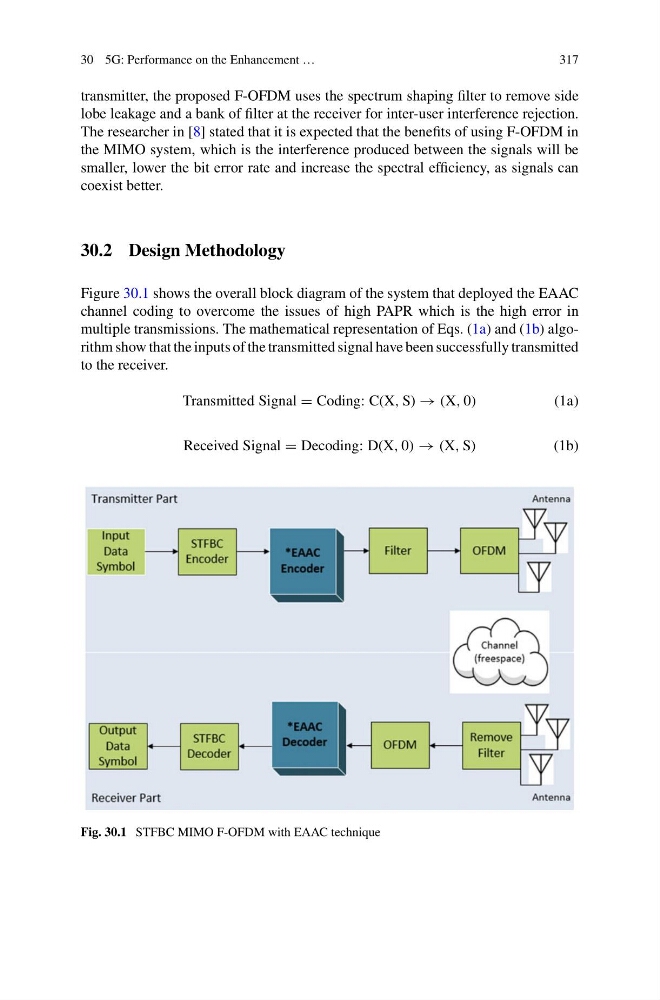
Figure 30.1 shows the overall block diagram of the system that deployed the EAAC
channel coding to overcome the issues of high PAPR which is the high error in
multiple transmissions. The mathematical representation of Eqs. (1a) and (1b) algorithm show that the inputs of the transmitted signal have been successfully transmitted
to the receiver.
Transmitted Signal = Coding: C(X, S) → (X, 0)
(1a)
Received Signal = Decoding: D(X, 0) → (X, S)
(1b)
Fig. 30.1 STFBC MIMO F-OFDM with EAAC technique
317
transmitter, the proposed F-OFDM uses the spectrum shaping filter to remove side
lobe leakage and a bank of filter at the receiver for inter-user interference rejection.
The researcher in [8] stated that it is expected that the benefits of using F-OFDM in
the MIMO system, which is the interference produced between the signals will be
smaller, lower the bit error rate and increase the spectral efficiency, as signals can
coexist better.
30.2 Design Methodology
Figure 30.1 shows the overall block diagram of the system that deployed the EAAC
channel coding to overcome the issues of high PAPR which is the high error in
multiple transmissions. The mathematical representation of Eqs. (1a) and (1b) algorithm show that the inputs of the transmitted signal have been successfully transmitted
to the receiver.
Transmitted Signal = Coding: C(X, S) → (X, 0)
(1a)
Received Signal = Decoding: D(X, 0) → (X, S)
(1b)
Fig. 30.1 STFBC MIMO F-OFDM with EAAC technique