

86
V. Sisodia et al.
6. Generation of point cloud data by scanning the formed part using 3D laser
scanner.
7. Import the point cloud data in SolidWorks software and measure the geometric
error in formed profile with target profile.
8. Interpretation of result, analysis of variance, development of mathematical
model.
9. Conducting the confirmation experiments for inspecting the adequacy of
developed model.
10. Optimization of process parameters to minimize geometric error (RMSE).
For the present work, tool diameter of 9 mm is used. It is hemispherical-ended
tool made of high-speed steel (HSS). Table 2 lists the values of parameters kept
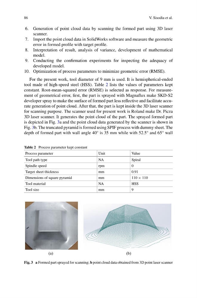
constant. Root-mean-squared error (RMSE) is selected as response. For measurement of geometrical error, first, the part is sprayed with Magnaflux make SKD-S2
developer spray to make the surface of formed part less reflective and facilitate accurate generation of point cloud. After that, the part is kept inside the 3D laser scanner
for scanning purpose. The scanner used for present work is Roland make Dr. Picza
3D laser scanner. It generates the point cloud of the part. The sprayed formed part
is depicted in Fig. 3a and the point cloud data generated by the scanner is shown in
Fig. 3b. The truncated pyramid is formed using SPIF process with dummy sheet. The
depth of formed part with wall angle 40° is 35 mm while with 52.5° and 65° wall
Table 2 Process parameter kept constant
Process parameter
Unit
Value
Tool path type
NA
Spiral
Spindle speed
rpm
0
Target sheet thickness
mm
0.91
Dimensions of square pyramid
mm
110 × 110
Tool material
NA
HSS
Tool size
mm
9
Fig. 3 a Formed part sprayed for scanning; b point cloud data obtained from 3D point laser scanner
V. Sisodia et al.
6. Generation of point cloud data by scanning the formed part using 3D laser
scanner.
7. Import the point cloud data in SolidWorks software and measure the geometric
error in formed profile with target profile.
8. Interpretation of result, analysis of variance, development of mathematical
model.
9. Conducting the confirmation experiments for inspecting the adequacy of
developed model.
10. Optimization of process parameters to minimize geometric error (RMSE).
For the present work, tool diameter of 9 mm is used. It is hemispherical-ended
tool made of high-speed steel (HSS). Table 2 lists the values of parameters kept
constant. Root-mean-squared error (RMSE) is selected as response. For measurement of geometrical error, first, the part is sprayed with Magnaflux make SKD-S2
developer spray to make the surface of formed part less reflective and facilitate accurate generation of point cloud. After that, the part is kept inside the 3D laser scanner
for scanning purpose. The scanner used for present work is Roland make Dr. Picza
3D laser scanner. It generates the point cloud of the part. The sprayed formed part
is depicted in Fig. 3a and the point cloud data generated by the scanner is shown in
Fig. 3b. The truncated pyramid is formed using SPIF process with dummy sheet. The
depth of formed part with wall angle 40° is 35 mm while with 52.5° and 65° wall
Table 2 Process parameter kept constant
Process parameter
Unit
Value
Tool path type
NA
Spiral
Spindle speed
rpm
0
Target sheet thickness
mm
0.91
Dimensions of square pyramid
mm
110 × 110
Tool material
NA
HSS
Tool size
mm
9
Fig. 3 a Formed part sprayed for scanning; b point cloud data obtained from 3D point laser scanner