

44
Y. L. Jain et al.
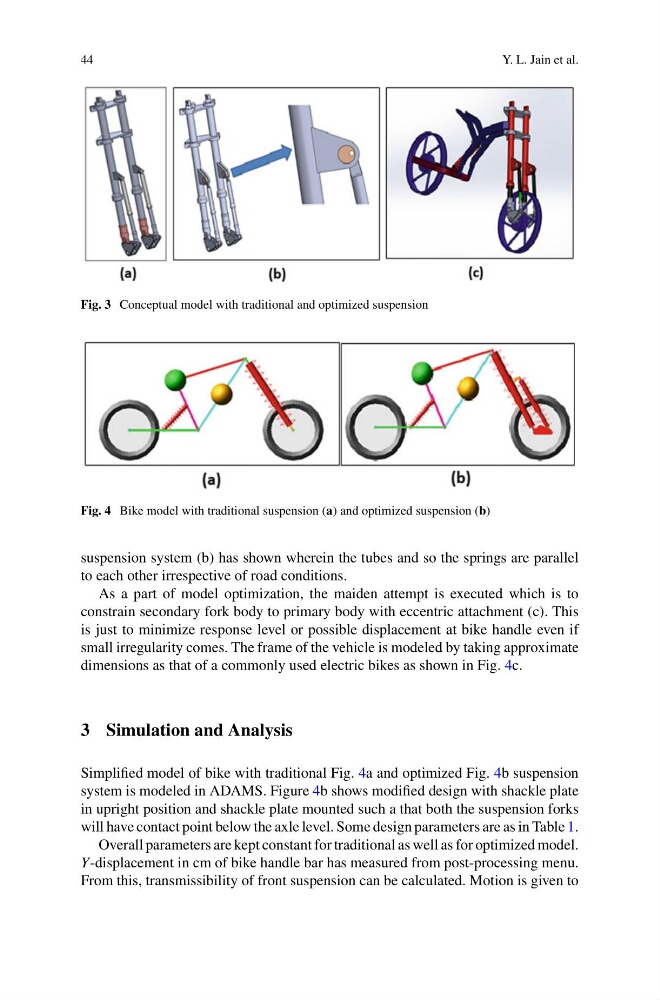
Fig. 3 Conceptual model with traditional and optimized suspension
Fig. 4 Bike model with traditional suspension (a) and optimized suspension (b)
suspension system (b) has shown wherein the tubes and so the springs are parallel
to each other irrespective of road conditions.
As a part of model optimization, the maiden attempt is executed which is to
constrain secondary fork body to primary body with eccentric attachment (c). This
is just to minimize response level or possible displacement at bike handle even if
small irregularity comes. The frame of the vehicle is modeled by taking approximate
dimensions as that of a commonly used electric bikes as shown in Fig. 4c.
3 Simulation and Analysis
Simplified model of bike with traditional Fig. 4a and optimized Fig. 4b suspension
system is modeled in ADAMS. Figure 4b shows modified design with shackle plate
in upright position and shackle plate mounted such a that both the suspension forks
will have contact point below the axle level. Some design parameters are as in Table 1.
Overall parameters are kept constant for traditional as well as for optimized model.
Y-displacement in cm of bike handle bar has measured from post-processing menu.
From this, transmissibility of front suspension can be calculated. Motion is given to
Y. L. Jain et al.
Fig. 3 Conceptual model with traditional and optimized suspension
Fig. 4 Bike model with traditional suspension (a) and optimized suspension (b)
suspension system (b) has shown wherein the tubes and so the springs are parallel
to each other irrespective of road conditions.
As a part of model optimization, the maiden attempt is executed which is to
constrain secondary fork body to primary body with eccentric attachment (c). This
is just to minimize response level or possible displacement at bike handle even if
small irregularity comes. The frame of the vehicle is modeled by taking approximate
dimensions as that of a commonly used electric bikes as shown in Fig. 4c.
3 Simulation and Analysis
Simplified model of bike with traditional Fig. 4a and optimized Fig. 4b suspension
system is modeled in ADAMS. Figure 4b shows modified design with shackle plate
in upright position and shackle plate mounted such a that both the suspension forks
will have contact point below the axle level. Some design parameters are as in Table 1.
Overall parameters are kept constant for traditional as well as for optimized model.
Y-displacement in cm of bike handle bar has measured from post-processing menu.
From this, transmissibility of front suspension can be calculated. Motion is given to