

Clutch Operating Mechanism for Disabled People with Leg Amputee
37
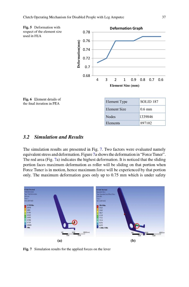
Fig. 5 Deformation with
respect of the element size
used in FEA
0.68
0.7
0.72
0.74
0.76
0.78
4
3
2
1 0.9 0.8 0.7 0.6
Deformation(mm)
Deformation Graph
Element Size (mm)
Fig. 6 Element details of
the final iteration in FEA
Element Type
SOLID 187
Element Size
0.6 mm
Nodes
1339846
Elements
897102
3.2 Simulation and Results
The simulation results are presented in Fig. 7. Two factors were evaluated namely
equivalent stress and deformation. Figure 7a shows the deformation in “Force Tuner”.
The red area (Fig. 7a) indicates the highest deformation. It is noticed that the sliding
portion faces maximum deformation as roller will be sliding on that portion when
Force Tuner is in motion, hence maximum force will be experienced by that portion
only. The maximum deformation goes only up to 0.75 mm which is under safety
Fig. 7 Simulation results for the applied forces on the lever
37
Fig. 5 Deformation with
respect of the element size
used in FEA
0.68
0.7
0.72
0.74
0.76
0.78
4
3
2
1 0.9 0.8 0.7 0.6
Deformation(mm)
Deformation Graph
Element Size (mm)
Fig. 6 Element details of
the final iteration in FEA
Element Type
SOLID 187
Element Size
0.6 mm
Nodes
1339846
Elements
897102
3.2 Simulation and Results
The simulation results are presented in Fig. 7. Two factors were evaluated namely
equivalent stress and deformation. Figure 7a shows the deformation in “Force Tuner”.
The red area (Fig. 7a) indicates the highest deformation. It is noticed that the sliding
portion faces maximum deformation as roller will be sliding on that portion when
Force Tuner is in motion, hence maximum force will be experienced by that portion
only. The maximum deformation goes only up to 0.75 mm which is under safety
Fig. 7 Simulation results for the applied forces on the lever