

36
R. K. Gupta et al.
M A = F/E
(2)
The lever 11 is connected to pulley 13 by flexible steel wire. The pulley 13 is fixed
with the rod 2 which in turn is mounted in inner bore of bearing 15 and is free to
rotate about its axis. The pulleys 14 and 13 on the rod 2 are connected to the control
handles with the help of cable. When the driver releases the handle, the clutch tends
to move upwards due to restoration force of spring and the clutch wire until it reaches
its initial position.
3.1 Finite Element Analysis (FEA)
The finite element analysis was conducted to check the required size, shape and
martial used for the fabrication of the lever. The finite element analysis of the lever
has been conducted to find out the risk-prone areas in it and improve the design if
needed. The axis of rotation of the lever is fixed where bearing is going to be fitted.
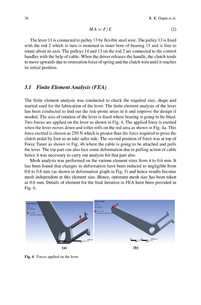
Two forces are applied on the lever as shown in Fig. 4. The applied force is exerted
when the lever moves down and roller rolls on the red area as shown in Fig. 4a. This
force exerted is chosen as 250 N which is greater than the force required to press the
clutch pedal by foot so as take safer side. The second position of force was at top of
Force Tuner as shown in Fig. 4b where the cable is going to be attached and pulls
the lever. The top part can also face some deformation due to pulling action of cable
hence it was necessary to carry out analysis for that part also.
Mesh analysis was performed on the various element sizes from 4 to 0.6 mm. It
has been found that changes in deformation have been reduced to negligible from
0.0 to 0.6 mm (as shown in deformation graph in Fig. 5) and hence results become
mesh independent at this element size. Hence, optimum mesh size has been taken
as 0.6 mm. Details of element for the final iteration in FEA have been provided in
Fig. 6.
Fig. 4 Forces applied on the lever
R. K. Gupta et al.
M A = F/E
(2)
The lever 11 is connected to pulley 13 by flexible steel wire. The pulley 13 is fixed
with the rod 2 which in turn is mounted in inner bore of bearing 15 and is free to
rotate about its axis. The pulleys 14 and 13 on the rod 2 are connected to the control
handles with the help of cable. When the driver releases the handle, the clutch tends
to move upwards due to restoration force of spring and the clutch wire until it reaches
its initial position.
3.1 Finite Element Analysis (FEA)
The finite element analysis was conducted to check the required size, shape and
martial used for the fabrication of the lever. The finite element analysis of the lever
has been conducted to find out the risk-prone areas in it and improve the design if
needed. The axis of rotation of the lever is fixed where bearing is going to be fitted.
Two forces are applied on the lever as shown in Fig. 4. The applied force is exerted
when the lever moves down and roller rolls on the red area as shown in Fig. 4a. This
force exerted is chosen as 250 N which is greater than the force required to press the
clutch pedal by foot so as take safer side. The second position of force was at top of
Force Tuner as shown in Fig. 4b where the cable is going to be attached and pulls
the lever. The top part can also face some deformation due to pulling action of cable
hence it was necessary to carry out analysis for that part also.
Mesh analysis was performed on the various element sizes from 4 to 0.6 mm. It
has been found that changes in deformation have been reduced to negligible from
0.0 to 0.6 mm (as shown in deformation graph in Fig. 5) and hence results become
mesh independent at this element size. Hence, optimum mesh size has been taken
as 0.6 mm. Details of element for the final iteration in FEA have been provided in
Fig. 6.
Fig. 4 Forces applied on the lever