

484
G. Sowmya Padukone et al.
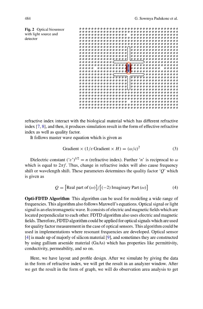
Fig. 2 Optical biosensor
with light source and
detector
refractive index interact with the biological material which has different refractive
index [7, 8], and then, it produces simulation result in the form of effective refractive
index as well as quality factor.
It follows master wave equation which is given as
Gradient × (1/ε Gradient × H ) = (ω/c)
2
(3)
Dielectric constant (‘ε’)
1/2
= n (refractive index). Further ‘n’ is reciprocal to ω
which is equal to 2π f . Thus, change in refractive index will also cause frequency
shift or wavelength shift. These parameters determines the quality factor ‘Q’ which
is given as
Q =
Real part of (ω)
/
(−2) Imaginary Part (ω)
(4)
Opti-FDTD Algorithm This algorithm can be used for modeling a wide range of
frequencies. This algorithm also follows Maxwell’s equations. Optical signal or light
signal is an electromagnetic wave. It consists of electric and magnetic fields which are
located perpendicular to each other. FDTD algorithm also uses electric and magnetic
fields. Therefore, FDTD algorithm could be applied for optical signals which are used
for quality factor measurement in the case of optical sensors. This algorithm could be
used in implementations where resonant frequencies are developed. Optical sensor
[4] is made up of majorly of silicon material [9], and sometimes they are constructed
by using gallium arsenide material (GaAs) which has properties like permittivity,
conductivity, permeability, and so on.
Here, we have layout and profile design. After we simulate by giving the data
in the form of refractive index, we will get the result in an analyzer window. After
we get the result in the form of graph, we will do observation area analysis to get
G. Sowmya Padukone et al.
Fig. 2 Optical biosensor
with light source and
detector
refractive index interact with the biological material which has different refractive
index [7, 8], and then, it produces simulation result in the form of effective refractive
index as well as quality factor.
It follows master wave equation which is given as
Gradient × (1/ε Gradient × H ) = (ω/c)
2
(3)
Dielectric constant (‘ε’)
1/2
= n (refractive index). Further ‘n’ is reciprocal to ω
which is equal to 2π f . Thus, change in refractive index will also cause frequency
shift or wavelength shift. These parameters determines the quality factor ‘Q’ which
is given as
Q =
Real part of (ω)
/
(−2) Imaginary Part (ω)
(4)
Opti-FDTD Algorithm This algorithm can be used for modeling a wide range of
frequencies. This algorithm also follows Maxwell’s equations. Optical signal or light
signal is an electromagnetic wave. It consists of electric and magnetic fields which are
located perpendicular to each other. FDTD algorithm also uses electric and magnetic
fields. Therefore, FDTD algorithm could be applied for optical signals which are used
for quality factor measurement in the case of optical sensors. This algorithm could be
used in implementations where resonant frequencies are developed. Optical sensor
[4] is made up of majorly of silicon material [9], and sometimes they are constructed
by using gallium arsenide material (GaAs) which has properties like permittivity,
conductivity, permeability, and so on.
Here, we have layout and profile design. After we simulate by giving the data
in the form of refractive index, we will get the result in an analyzer window. After
we get the result in the form of graph, we will do observation area analysis to get