

Experimental and Numerical Investigation of Non-reacting Flow …
135
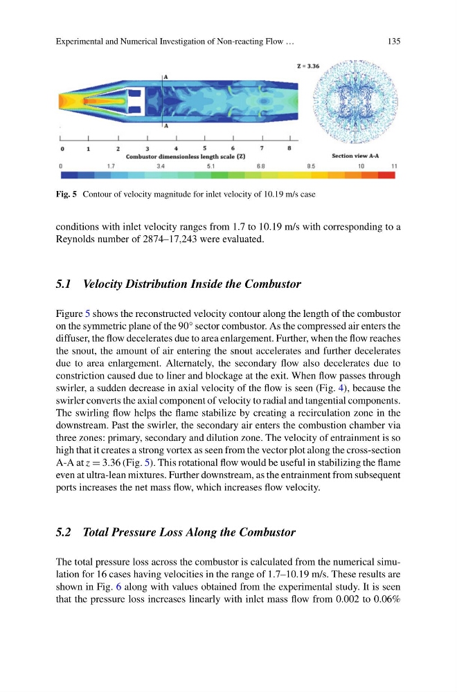
Fig. 5 Contour of velocity magnitude for inlet velocity of 10.19 m/s case
conditions with inlet velocity ranges from 1.7 to 10.19 m/s with corresponding to a
Reynolds number of 2874–17,243 were evaluated.
5.1 Velocity Distribution Inside the Combustor
Figure 5 shows the reconstructed velocity contour along the length of the combustor
on the symmetric plane of the 90° sector combustor. As the compressed air enters the
diffuser, the flow decelerates due to area enlargement. Further, when the flow reaches
the snout, the amount of air entering the snout accelerates and further decelerates
due to area enlargement. Alternately, the secondary flow also decelerates due to
constriction caused due to liner and blockage at the exit. When flow passes through
swirler, a sudden decrease in axial velocity of the flow is seen (Fig. 4), because the
swirler converts the axial component of velocity to radial and tangential components.
The swirling flow helps the flame stabilize by creating a recirculation zone in the
downstream. Past the swirler, the secondary air enters the combustion chamber via
three zones: primary, secondary and dilution zone. The velocity of entrainment is so
high that it creates a strong vortex as seen from the vector plot along the cross-section
A-A at z = 3.36 (Fig. 5). This rotational flow would be useful in stabilizing the flame
even at ultra-lean mixtures. Further downstream, as the entrainment from subsequent
ports increases the net mass flow, which increases flow velocity.
5.2 Total Pressure Loss Along the Combustor
The total pressure loss across the combustor is calculated from the numerical simulation for 16 cases having velocities in the range of 1.7–10.19 m/s. These results are
shown in Fig. 6 along with values obtained from the experimental study. It is seen
that the pressure loss increases linearly with inlet mass flow from 0.002 to 0.06%
135
Fig. 5 Contour of velocity magnitude for inlet velocity of 10.19 m/s case
conditions with inlet velocity ranges from 1.7 to 10.19 m/s with corresponding to a
Reynolds number of 2874–17,243 were evaluated.
5.1 Velocity Distribution Inside the Combustor
Figure 5 shows the reconstructed velocity contour along the length of the combustor
on the symmetric plane of the 90° sector combustor. As the compressed air enters the
diffuser, the flow decelerates due to area enlargement. Further, when the flow reaches
the snout, the amount of air entering the snout accelerates and further decelerates
due to area enlargement. Alternately, the secondary flow also decelerates due to
constriction caused due to liner and blockage at the exit. When flow passes through
swirler, a sudden decrease in axial velocity of the flow is seen (Fig. 4), because the
swirler converts the axial component of velocity to radial and tangential components.
The swirling flow helps the flame stabilize by creating a recirculation zone in the
downstream. Past the swirler, the secondary air enters the combustion chamber via
three zones: primary, secondary and dilution zone. The velocity of entrainment is so
high that it creates a strong vortex as seen from the vector plot along the cross-section
A-A at z = 3.36 (Fig. 5). This rotational flow would be useful in stabilizing the flame
even at ultra-lean mixtures. Further downstream, as the entrainment from subsequent
ports increases the net mass flow, which increases flow velocity.
5.2 Total Pressure Loss Along the Combustor
The total pressure loss across the combustor is calculated from the numerical simulation for 16 cases having velocities in the range of 1.7–10.19 m/s. These results are
shown in Fig. 6 along with values obtained from the experimental study. It is seen
that the pressure loss increases linearly with inlet mass flow from 0.002 to 0.06%