

Thermal Distribution on Gas Turbine Blade Using Thermal Paint
107
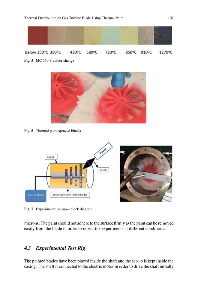
Fig. 5 MC 350-8 colour change
Fig. 6 Thermal paint sprayed blades
Fig. 7 Experimental set-up---block diagram
microns. The paint should not adhere to the surface firmly as the paint can be removed
easily from the blade in order to repeat the experiments at different conditions.
4.3 Experimental Test Rig
The painted blades have been placed inside the shaft and the set-up is kept inside the
casing. The shaft is connected to the electric motor in order to drive the shaft initially
107
Fig. 5 MC 350-8 colour change
Fig. 6 Thermal paint sprayed blades
Fig. 7 Experimental set-up---block diagram
microns. The paint should not adhere to the surface firmly as the paint can be removed
easily from the blade in order to repeat the experiments at different conditions.
4.3 Experimental Test Rig
The painted blades have been placed inside the shaft and the set-up is kept inside the
casing. The shaft is connected to the electric motor in order to drive the shaft initially