

5.3 Numeral Examples
89
0
20
40
60
80
100
0.5
1
1.5
2
2.5
3
3.5
t/s
mode
mode
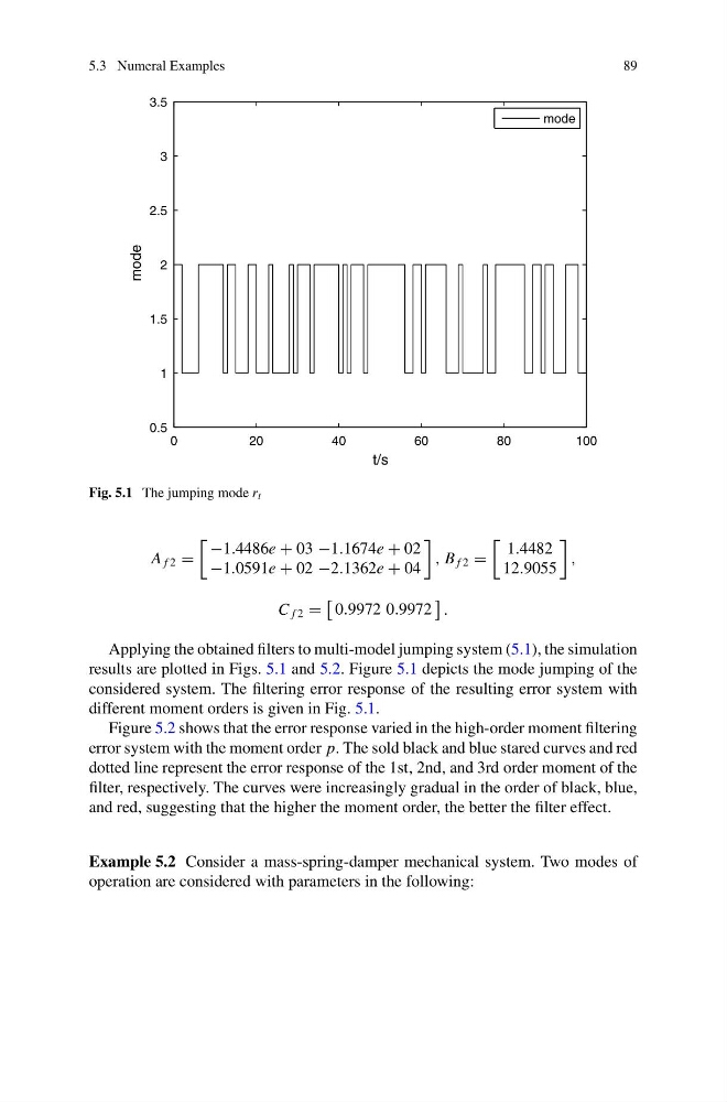
Fig. 5.1 The jumping mode r t
A f 2 =
−1.4486e + 03 −1.1674e + 02
−1.0591e + 02 −2.1362e + 04
, B f 2 =
1.4482
12.9055
,
C f 2 =
0.9972 0.9972
.
Applying the obtained filters to multi-model jumping system (5.1), the simulation
results are plotted in Figs. 5.1 and 5.2. Figure 5.1 depicts the mode jumping of the
considered system. The filtering error response of the resulting error system with
different moment orders is given in Fig. 5.1.
Figure 5.2 shows that the error response varied in the high-order moment filtering
error system with the moment order p. The sold black and blue stared curves and red
dotted line represent the error response of the 1st, 2nd, and 3rd order moment of the
filter, respectively. The curves were increasingly gradual in the order of black, blue,
and red, suggesting that the higher the moment order, the better the filter effect.
Example 5.2 Consider a mass-spring-damper mechanical system. Two modes of
operation are considered with parameters in the following:
89
0
20
40
60
80
100
0.5
1
1.5
2
2.5
3
3.5
t/s
mode
mode
Fig. 5.1 The jumping mode r t
A f 2 =
−1.4486e + 03 −1.1674e + 02
−1.0591e + 02 −2.1362e + 04
, B f 2 =
1.4482
12.9055
,
C f 2 =
0.9972 0.9972
.
Applying the obtained filters to multi-model jumping system (5.1), the simulation
results are plotted in Figs. 5.1 and 5.2. Figure 5.1 depicts the mode jumping of the
considered system. The filtering error response of the resulting error system with
different moment orders is given in Fig. 5.1.
Figure 5.2 shows that the error response varied in the high-order moment filtering
error system with the moment order p. The sold black and blue stared curves and red
dotted line represent the error response of the 1st, 2nd, and 3rd order moment of the
filter, respectively. The curves were increasingly gradual in the order of black, blue,
and red, suggesting that the higher the moment order, the better the filter effect.
Example 5.2 Consider a mass-spring-damper mechanical system. Two modes of
operation are considered with parameters in the following: