

280
D. Escudero
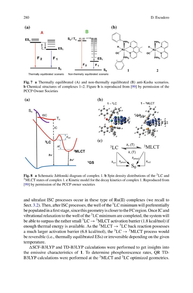
Fig. 7 a Thermally equilibrated (A) and non-thermally equilibrated (B) anti-Kasha scenarios.
b Chemical structures of complexes 1–2. Figure b is reproduced from [99] by permission of the
PCCP Owner Societies
Fig. 8 a Schematic Jablonski diagram of complex 1. b Spin density distributions of the 3 LC and
3 MLCT states of complex 1. c Kinetic model for the decay kinetics of complex 1. Reproduced from
[99] by permission of the PCCP owner societies
and ultrafast ISC processes occur in these type of Ru(II) complexes (we recall to
Sect. 3.2). Then, after ISC processes, the well of the
3 LC minimum will preferentially
be populated in a first stage, since this geometry is closer to the FC region. Once IC and
vibrational relaxation to the well of the
3 LC minimum are completed, the system will
be able to surpass the rather small
3 LC →
3 MLCT activation barrier (1.8 kcal/mol) if
enough thermal energy is available. As the
3 MLCT →
3 LC back reaction possesses
a much larger activation barrier (6.8 kcal/mol), the
3 LC →
3 MLCT process would
be reversible (i.e., thermally equilibrated ESs) or irreversible depending on the given
temperature.
SCF-B3LYP and TD-B3LYP calculations were performed to get insights into
the emissive characteristics of 1. To determine phosphorescence rates, QR TDB3LYP calculations were performed at the
3 MLCT and
3 LC optimized geometries.
D. Escudero
Fig. 7 a Thermally equilibrated (A) and non-thermally equilibrated (B) anti-Kasha scenarios.
b Chemical structures of complexes 1–2. Figure b is reproduced from [99] by permission of the
PCCP Owner Societies
Fig. 8 a Schematic Jablonski diagram of complex 1. b Spin density distributions of the 3 LC and
3 MLCT states of complex 1. c Kinetic model for the decay kinetics of complex 1. Reproduced from
[99] by permission of the PCCP owner societies
and ultrafast ISC processes occur in these type of Ru(II) complexes (we recall to
Sect. 3.2). Then, after ISC processes, the well of the
3 LC minimum will preferentially
be populated in a first stage, since this geometry is closer to the FC region. Once IC and
vibrational relaxation to the well of the
3 LC minimum are completed, the system will
be able to surpass the rather small
3 LC →
3 MLCT activation barrier (1.8 kcal/mol) if
enough thermal energy is available. As the
3 MLCT →
3 LC back reaction possesses
a much larger activation barrier (6.8 kcal/mol), the
3 LC →
3 MLCT process would
be reversible (i.e., thermally equilibrated ESs) or irreversible depending on the given
temperature.
SCF-B3LYP and TD-B3LYP calculations were performed to get insights into
the emissive characteristics of 1. To determine phosphorescence rates, QR TDB3LYP calculations were performed at the
3 MLCT and
3 LC optimized geometries.