

76
6 Feynman Diagrams
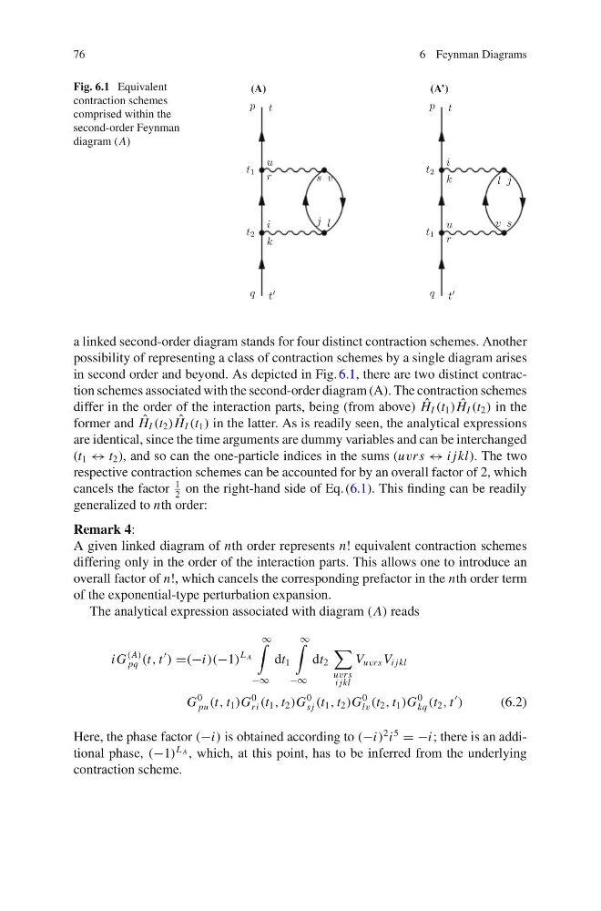
Fig. 6.1 Equivalent
contraction schemes
comprised within the
second-order Feynman
diagram (A)
(A)
(A’)
a linked second-order diagram stands for four distinct contraction schemes. Another
possibility of representing a class of contraction schemes by a single diagram arises
in second order and beyond. As depicted in Fig. 6.1, there are two distinct contraction schemes associated with the second-order diagram (A). The contraction schemes
differ in the order of the interaction parts, being (from above) ˆ
H I (t 1 ) ˆ
H I (t 2 ) in the
former and ˆ
H I (t 2 ) ˆ
H I (t 1 ) in the latter. As is readily seen, the analytical expressions
are identical, since the time arguments are dummy variables and can be interchanged
(t 1 ↔ t 2 ), and so can the one-particle indices in the sums (uvrs ↔ i jkl). The two
respective contraction schemes can be accounted for by an overall factor of 2, which
cancels the factor
1
2
on the right-hand side of Eq. (6.1). This finding can be readily
generalized to nth order:
Remark 4:
A given linked diagram of nth order represents n! equivalent contraction schemes
differing only in the order of the interaction parts. This allows one to introduce an
overall factor of n!, which cancels the corresponding prefactor in the nth order term
of the exponential-type perturbation expansion.
The analytical expression associated with diagram (A) reads
i G
(A)
pq (t, t
) =(−i)(−1)
L A
∞
−∞
dt 1
∞
−∞
dt 2
uvrs
i jkl
V uvrs V i jkl
G
0
pu (t, t 1 )G
0
ri (t 1 , t 2 )G
0
s j (t 1 , t 2 )G
0
lv (t 2 , t 1 )G
0
kq (t 2 , t
)
(6.2)
Here, the phase factor (−i) is obtained according to (−i)
2 i
5
= −i; there is an additional phase, (−1)
L A , which, at this point, has to be inferred from the underlying
contraction scheme.
6 Feynman Diagrams
Fig. 6.1 Equivalent
contraction schemes
comprised within the
second-order Feynman
diagram (A)
(A)
(A’)
a linked second-order diagram stands for four distinct contraction schemes. Another
possibility of representing a class of contraction schemes by a single diagram arises
in second order and beyond. As depicted in Fig. 6.1, there are two distinct contraction schemes associated with the second-order diagram (A). The contraction schemes
differ in the order of the interaction parts, being (from above) ˆ
H I (t 1 ) ˆ
H I (t 2 ) in the
former and ˆ
H I (t 2 ) ˆ
H I (t 1 ) in the latter. As is readily seen, the analytical expressions
are identical, since the time arguments are dummy variables and can be interchanged
(t 1 ↔ t 2 ), and so can the one-particle indices in the sums (uvrs ↔ i jkl). The two
respective contraction schemes can be accounted for by an overall factor of 2, which
cancels the factor
1
2
on the right-hand side of Eq. (6.1). This finding can be readily
generalized to nth order:
Remark 4:
A given linked diagram of nth order represents n! equivalent contraction schemes
differing only in the order of the interaction parts. This allows one to introduce an
overall factor of n!, which cancels the corresponding prefactor in the nth order term
of the exponential-type perturbation expansion.
The analytical expression associated with diagram (A) reads
i G
(A)
pq (t, t
) =(−i)(−1)
L A
∞
−∞
dt 1
∞
−∞
dt 2
uvrs
i jkl
V uvrs V i jkl
G
0
pu (t, t 1 )G
0
ri (t 1 , t 2 )G
0
s j (t 1 , t 2 )G
0
lv (t 2 , t 1 )G
0
kq (t 2 , t
)
(6.2)
Here, the phase factor (−i) is obtained according to (−i)
2 i
5
= −i; there is an additional phase, (−1)
L A , which, at this point, has to be inferred from the underlying
contraction scheme.