

66
5 Introducing Diagrams
one can resort to a graphical representation in terms of diagrams, as first introduced
by Feynman [2] in the context of quantum electrodynamics (QED).
To introduce the diagrammatic formulation, let us consider the zeroth- and firstorder terms in the numerator i ˜
G pq (t, t
). For simplicity, we will suppose in the
following that the interaction hamiltonian (5.1) consists only of the Coulomb part,
which in turn means that one has to allow for a non-diagonal free one-particle part
ˆ
H 0 . The case of the full interaction hamiltonian, ˆ
H I = ˆ
W + ˆ
V , comprising also a
one-particle part, will be discussed in Sect. 6.2.
Zeroth Order:
i ˜
G
0
pq (t, t
) = i G
0
pq (t, t
) = = 0 | ˆ
T T T
c p (t)c
†
q (t
)
| 0 = c p (t)
c
†
q (t
)
(5.20)
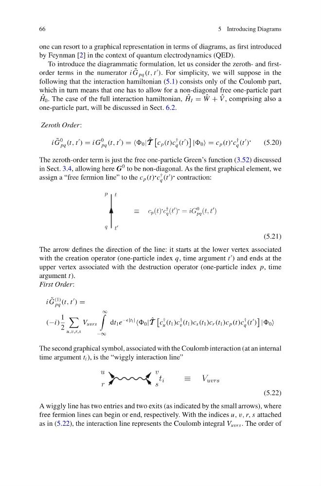
The zeroth-order term is just the free one-particle Green’s function (3.52) discussed
in Sect. 3.4, allowing here G
0 to be non-diagonal. As the first graphical element, we
assign a “free fermion line” to the c p (t)
c
†
q (t
)
contraction:
(5.21)
The arrow defines the direction of the line: it starts at the lower vertex associated
with the creation operator (one-particle index q, time argument t
) and ends at the
upper vertex associated with the destruction operator (one-particle index p, time
argument t).
First Order:
i ˜
G
(1)
pq (t, t
) =
(−i)
1
2
u,v,r,s
V uvrs
∞
−∞
dt 1 e
−|t 1 |
0 | ˆ
T T T
c
†
u (t 1 )c
†
v (t 1 )c s (t 1 )c r (t 1 )c p (t)c
†
q (t
)
| 0
The second graphical symbol, associated with the Coulomb interaction (at an internal
time argument t i ), is the “wiggly interaction line”
(5.22)
A wiggly line has two entries and two exits (as indicated by the small arrows), where
free fermion lines can begin or end, respectively. With the indices u, v, r, s attached
as in (5.22), the interaction line represents the Coulomb integral V uvrs . The order of
5 Introducing Diagrams
one can resort to a graphical representation in terms of diagrams, as first introduced
by Feynman [2] in the context of quantum electrodynamics (QED).
To introduce the diagrammatic formulation, let us consider the zeroth- and firstorder terms in the numerator i ˜
G pq (t, t
). For simplicity, we will suppose in the
following that the interaction hamiltonian (5.1) consists only of the Coulomb part,
which in turn means that one has to allow for a non-diagonal free one-particle part
ˆ
H 0 . The case of the full interaction hamiltonian, ˆ
H I = ˆ
W + ˆ
V , comprising also a
one-particle part, will be discussed in Sect. 6.2.
Zeroth Order:
i ˜
G
0
pq (t, t
) = i G
0
pq (t, t
) = = 0 | ˆ
T T T
c p (t)c
†
q (t
)
| 0 = c p (t)
c
†
q (t
)
(5.20)
The zeroth-order term is just the free one-particle Green’s function (3.52) discussed
in Sect. 3.4, allowing here G
0 to be non-diagonal. As the first graphical element, we
assign a “free fermion line” to the c p (t)
c
†
q (t
)
contraction:
(5.21)
The arrow defines the direction of the line: it starts at the lower vertex associated
with the creation operator (one-particle index q, time argument t
) and ends at the
upper vertex associated with the destruction operator (one-particle index p, time
argument t).
First Order:
i ˜
G
(1)
pq (t, t
) =
(−i)
1
2
u,v,r,s
V uvrs
∞
−∞
dt 1 e
−|t 1 |
0 | ˆ
T T T
c
†
u (t 1 )c
†
v (t 1 )c s (t 1 )c r (t 1 )c p (t)c
†
q (t
)
| 0
The second graphical symbol, associated with the Coulomb interaction (at an internal
time argument t i ), is the “wiggly interaction line”
(5.22)
A wiggly line has two entries and two exits (as indicated by the small arrows), where
free fermion lines can begin or end, respectively. With the indices u, v, r, s attached
as in (5.22), the interaction line represents the Coulomb integral V uvrs . The order of