

208
14 ADC and ISR Approaches to the Polarization Propagator
14.2 Explicit ADC Schemes for the Polarization Propagator
In the ADC formulation, the secular matrix is conveniently written as
M = K + C
= K + C
(1)
+ C
(2)
+ . . .
(14.17)
where
K = M
(0)
(14.18)
denotes the zeroth-order part of M. According to
M
(0)
I J = = I | ˆ
H 0 − E
(0)
0 | J = K I J
(14.19)
K is the diagonal matrix of HF excitation energies,
K ak,ak = a − k
K abkl,abkl = a + b − k − l
. . .
(14.20)
In zeroth order, the ADC term
(0)+
(ω) = f
(0)†
(ω − K )
−1 f
(0)
(14.21)
is to be compared with the diagrammatic expression (Eq. 13.19),
(0)+
ak,a k (ω) = δ aa δ kk (ω − a + k )
−1
(14.22)
from which one obtains
f
(0)
ak,rs = δ ar δ ks
(14.23)
Moreover, the comparison in zeroth order implies f
(0)
μ = 0 for μ > 1; that is, the
zeroth-order matrix elements f
(0)
I,rs vanish unless I is a 1 p-1h configuration.
First-Order ADC Scheme
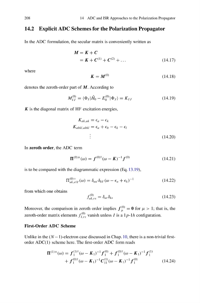
Unlike in the (N −1)-electron case discussed in Chap. 10, there is a non-trivial firstorder ADC(1) scheme here. The first-order ADC form reads
(1)+
(ω) = f
(1)†
1 (ω − K 1 )
−1 f
(0)
1 + f
(0)†
1 (ω − K 1 )
−1 f
(1)
1
+ f
(0)†
1 (ω − K 1 )
−1 C
(1)
11 (ω − K 1 )
−1 f
(0)
1
(14.24)
14 ADC and ISR Approaches to the Polarization Propagator
14.2 Explicit ADC Schemes for the Polarization Propagator
In the ADC formulation, the secular matrix is conveniently written as
M = K + C
= K + C
(1)
+ C
(2)
+ . . .
(14.17)
where
K = M
(0)
(14.18)
denotes the zeroth-order part of M. According to
M
(0)
I J = = I | ˆ
H 0 − E
(0)
0 | J = K I J
(14.19)
K is the diagonal matrix of HF excitation energies,
K ak,ak = a − k
K abkl,abkl = a + b − k − l
. . .
(14.20)
In zeroth order, the ADC term
(0)+
(ω) = f
(0)†
(ω − K )
−1 f
(0)
(14.21)
is to be compared with the diagrammatic expression (Eq. 13.19),
(0)+
ak,a k (ω) = δ aa δ kk (ω − a + k )
−1
(14.22)
from which one obtains
f
(0)
ak,rs = δ ar δ ks
(14.23)
Moreover, the comparison in zeroth order implies f
(0)
μ = 0 for μ > 1; that is, the
zeroth-order matrix elements f
(0)
I,rs vanish unless I is a 1 p-1h configuration.
First-Order ADC Scheme
Unlike in the (N −1)-electron case discussed in Chap. 10, there is a non-trivial firstorder ADC(1) scheme here. The first-order ADC form reads
(1)+
(ω) = f
(1)†
1 (ω − K 1 )
−1 f
(0)
1 + f
(0)†
1 (ω − K 1 )
−1 f
(1)
1
+ f
(0)†
1 (ω − K 1 )
−1 C
(1)
11 (ω − K 1 )
−1 f
(0)
1
(14.24)