

adsorption and the selectivity toward CH 4 , Pan et al. [47] developed a 5-nm-thick
carbon layer coated on In 2 O 3 nanobelt coupled with Pt NP+ loadings. The glucose
was used as the carbon source and the carbon layer was formed at 600
C under the
Ar atmosphere. Afterward, the Pt NPs were deposited on the surface of carbon layer
through a photo-deposition method. The loading amount of carbon layer and Pt are
8% and 2%, respectively. Another classic dual cocatalysts structure of Pt@Cu x O
loaded on TiO 2 (p25) was proposed by Zhai and coworkers [41]. At first, Pt–TiO 2
was first prepared by photoreduction of H 2 PtCl 6 in the TiO 2 suspension; afterward,
the Cu species were deposited on the Pt surface under the illumination and using the
CuSO 4 as the precursor. The Cu is easily oxidized into Cu
1 in air; therefore, the Cu
existed as Cu x O form. Moreover, prolonging the photo-deposition time of Cu
species will increase the Cu x O coverage on Pt NPs; the 5-h irradiation will form a
complete Pt@Cu x O core–shell structure.
The all-solid-state Z-scheme photocatalysts could take advantage of more negative reduction potential electrons and more positive oxidation potential holes from
different semiconductors counterparts, thus attract more and more attention in
CO2PR. Generally speaking, the photosystem II (oxidation part PSII) and photosystem I (reduction part PSI) are connected by a conductor. Li et al. [45] developed
an elegant all-solid Z-scheme WO 3 /Au/In 2 S 3 nanowire photocatalyst; the WO 3
nanowire was first grown on the tungsten foil under Ar flow with WO 3 powder as
precursor, then Au NPs were deposited on WO 3 nanowire by plasma sputtering
method, and the In 2 S 3 shell coated on Au surface was finally obtained through a
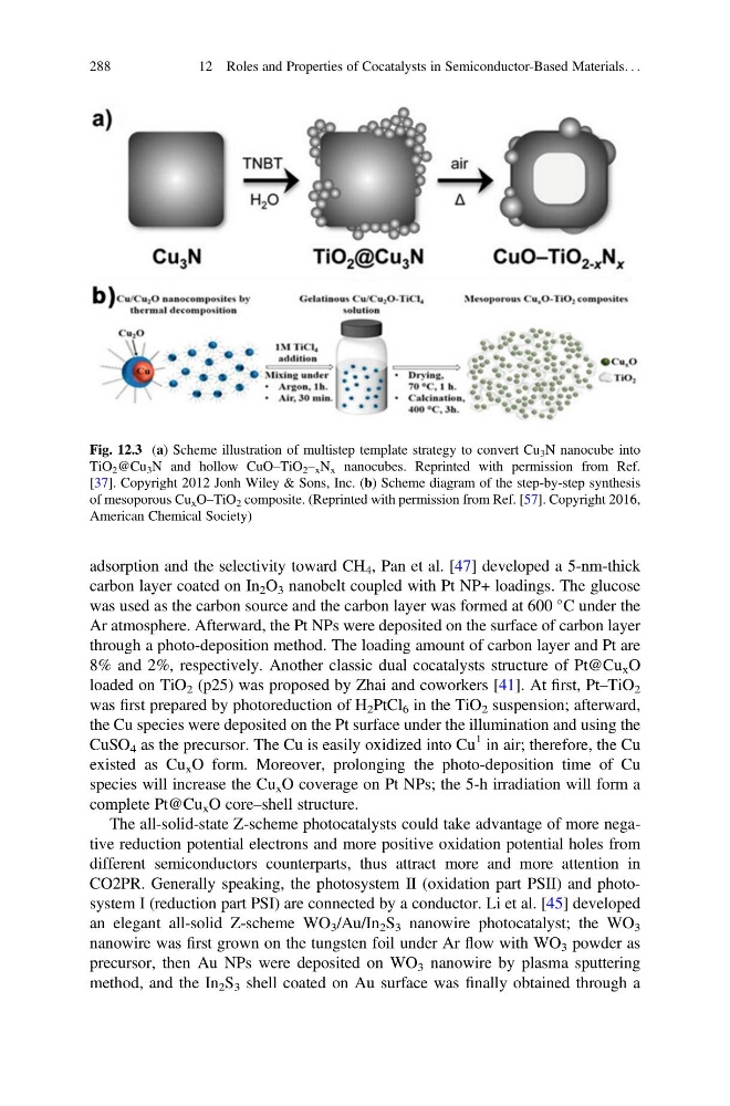
Fig. 12.3 (a) Scheme illustration of multistep template strategy to convert Cu 3 N nanocube into
TiO 2 @Cu 3 N and hollow CuO–TiO 2 – x N x nanocubes. Reprinted with permission from Ref.
[37]. Copyright 2012 Jonh Wiley & Sons, Inc. (b) Scheme diagram of the step-by-step synthesis
of mesoporous Cu x O–TiO 2 composite. (Reprinted with permission from Ref. [57]. Copyright 2016,
American Chemical Society)
288
12 Roles and Properties of Cocatalysts in Semiconductor-Based Materials. . .
carbon layer coated on In 2 O 3 nanobelt coupled with Pt NP+ loadings. The glucose
was used as the carbon source and the carbon layer was formed at 600
C under the
Ar atmosphere. Afterward, the Pt NPs were deposited on the surface of carbon layer
through a photo-deposition method. The loading amount of carbon layer and Pt are
8% and 2%, respectively. Another classic dual cocatalysts structure of Pt@Cu x O
loaded on TiO 2 (p25) was proposed by Zhai and coworkers [41]. At first, Pt–TiO 2
was first prepared by photoreduction of H 2 PtCl 6 in the TiO 2 suspension; afterward,
the Cu species were deposited on the Pt surface under the illumination and using the
CuSO 4 as the precursor. The Cu is easily oxidized into Cu
1 in air; therefore, the Cu
existed as Cu x O form. Moreover, prolonging the photo-deposition time of Cu
species will increase the Cu x O coverage on Pt NPs; the 5-h irradiation will form a
complete Pt@Cu x O core–shell structure.
The all-solid-state Z-scheme photocatalysts could take advantage of more negative reduction potential electrons and more positive oxidation potential holes from
different semiconductors counterparts, thus attract more and more attention in
CO2PR. Generally speaking, the photosystem II (oxidation part PSII) and photosystem I (reduction part PSI) are connected by a conductor. Li et al. [45] developed
an elegant all-solid Z-scheme WO 3 /Au/In 2 S 3 nanowire photocatalyst; the WO 3
nanowire was first grown on the tungsten foil under Ar flow with WO 3 powder as
precursor, then Au NPs were deposited on WO 3 nanowire by plasma sputtering
method, and the In 2 S 3 shell coated on Au surface was finally obtained through a
Fig. 12.3 (a) Scheme illustration of multistep template strategy to convert Cu 3 N nanocube into
TiO 2 @Cu 3 N and hollow CuO–TiO 2 – x N x nanocubes. Reprinted with permission from Ref.
[37]. Copyright 2012 Jonh Wiley & Sons, Inc. (b) Scheme diagram of the step-by-step synthesis
of mesoporous Cu x O–TiO 2 composite. (Reprinted with permission from Ref. [57]. Copyright 2016,
American Chemical Society)
288
12 Roles and Properties of Cocatalysts in Semiconductor-Based Materials. . .