

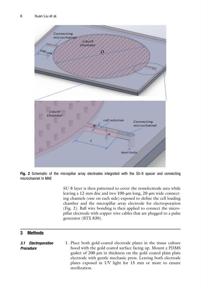
SU-8 layer is then patterned to cover the nonelectrode area while
leaving a 12-mm disc and two 100-μm long, 20-μm wide connecting channels (one on each side) exposed to define the cell loading
chamber and the micropillar array electrode for electroporation
(Fig. 2). Ball wire bonding is then applied to connect the micropillar electrode with copper wire cables that are plugged to a pulse
generator (BTX 830).
3 Methods
3.1 Electroporation
Procedure
1. Place both gold-coated electrode plates in the tissue culture
hood with the gold coated surface facing up. Mount a PDMS
gasket of 200 μm in thickness on the gold coated plain plate
electrode with gentle mechanic press. Leaving both electrode
plates exposed in UV light for 15 min or more to ensure
sterilization.
Fig. 2 Schematic of the micropillar array electrodes integrated with the SU-8 spacer and connecting
microchannel in MAE
6
Xuan Liu et al.
leaving a 12-mm disc and two 100-μm long, 20-μm wide connecting channels (one on each side) exposed to define the cell loading
chamber and the micropillar array electrode for electroporation
(Fig. 2). Ball wire bonding is then applied to connect the micropillar electrode with copper wire cables that are plugged to a pulse
generator (BTX 830).
3 Methods
3.1 Electroporation
Procedure
1. Place both gold-coated electrode plates in the tissue culture
hood with the gold coated surface facing up. Mount a PDMS
gasket of 200 μm in thickness on the gold coated plain plate
electrode with gentle mechanic press. Leaving both electrode
plates exposed in UV light for 15 min or more to ensure
sterilization.
Fig. 2 Schematic of the micropillar array electrodes integrated with the SU-8 spacer and connecting
microchannel in MAE
6
Xuan Liu et al.