

162
L. González et al.
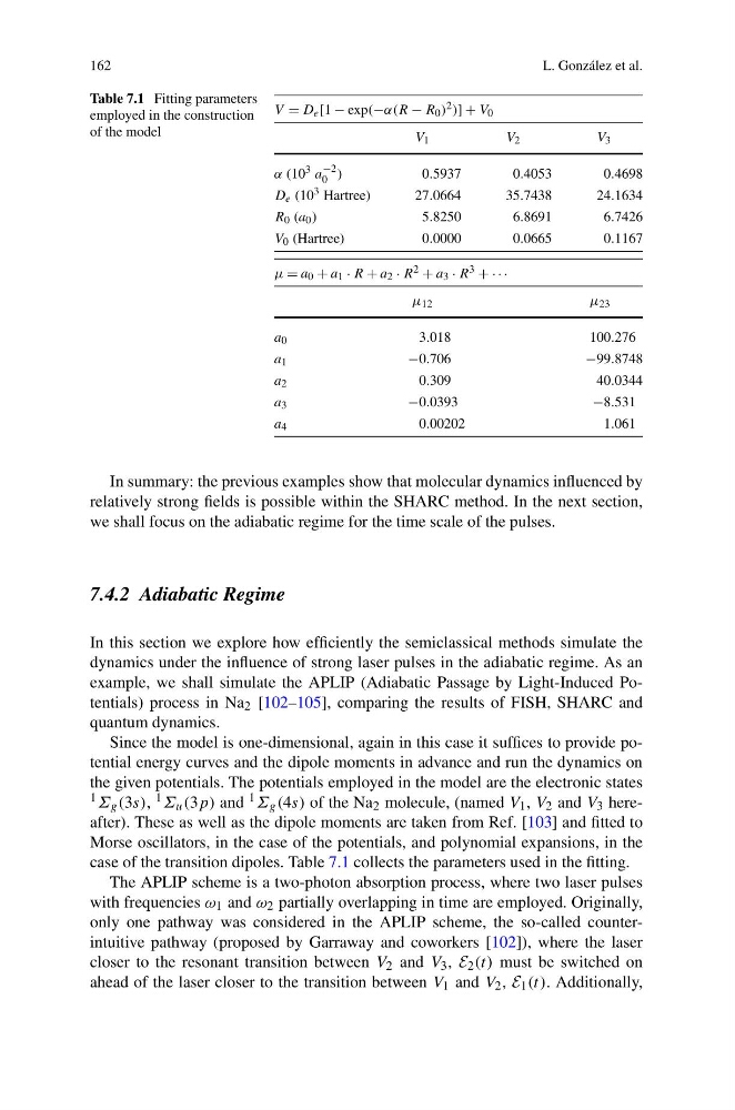
Table 7.1 Fitting parameters
employed in the construction
of the model
V = D e [1 − exp(−α(R − R 0 ) 2 )] + V 0
V 1
V 2
V 3
α (10 3 a
−2
0 )
0 .5937
0.4053
0.4698
D e (10 3 Hartree)
27.0664
35.7438
24.1634
R 0 (a 0 )
5 .8250
6.8691
6.7426
V 0 (Hartree)
0.0000
0.0665
0.1167
μ = a 0 + a 1 · R + a 2 · R 2 + a 3 · R 3 + · · ·
μ 12
μ 23
a 0
3.018
100.276
a 1
−0.706
−99.8748
a 2
0.309
40.0344
a 3
−0.0393
−8.531
a 4
0.00202
1.061
In summary: the previous examples show that molecular dynamics influenced by
relatively strong fields is possible within the SHARC method. In the next section,
we shall focus on the adiabatic regime for the time scale of the pulses.
7.4.2 Adiabatic Regime
In this section we explore how efficiently the semiclassical methods simulate the
dynamics under the influence of strong laser pulses in the adiabatic regime. As an
example, we shall simulate the APLIP (Adiabatic Passage by Light-Induced Potentials) process in Na 2 [102–105], comparing the results of FISH, SHARC and
quantum dynamics.
Since the model is one-dimensional, again in this case it suffices to provide potential energy curves and the dipole moments in advance and run the dynamics on
the given potentials. The potentials employed in the model are the electronic states
1 Σ g (3s), 1 Σ u (3p) and 1 Σ g (4s) of the Na 2 molecule, (named V 1 , V 2 and V 3 hereafter). These as well as the dipole moments are taken from Ref. [103] and fitted to
Morse oscillators, in the case of the potentials, and polynomial expansions, in the
case of the transition dipoles. Table 7.1 collects the parameters used in the fitting.
The APLIP scheme is a two-photon absorption process, where two laser pulses
with frequencies ω 1 and ω 2 partially overlapping in time are employed. Originally,
only one pathway was considered in the APLIP scheme, the so-called counterintuitive pathway (proposed by Garraway and coworkers [102]), where the laser
closer to the resonant transition between V 2 and V 3 , E 2 (t) must be switched on
ahead of the laser closer to the transition between V 1 and V 2 , E 1 (t). Additionally,
L. González et al.
Table 7.1 Fitting parameters
employed in the construction
of the model
V = D e [1 − exp(−α(R − R 0 ) 2 )] + V 0
V 1
V 2
V 3
α (10 3 a
−2
0 )
0 .5937
0.4053
0.4698
D e (10 3 Hartree)
27.0664
35.7438
24.1634
R 0 (a 0 )
5 .8250
6.8691
6.7426
V 0 (Hartree)
0.0000
0.0665
0.1167
μ = a 0 + a 1 · R + a 2 · R 2 + a 3 · R 3 + · · ·
μ 12
μ 23
a 0
3.018
100.276
a 1
−0.706
−99.8748
a 2
0.309
40.0344
a 3
−0.0393
−8.531
a 4
0.00202
1.061
In summary: the previous examples show that molecular dynamics influenced by
relatively strong fields is possible within the SHARC method. In the next section,
we shall focus on the adiabatic regime for the time scale of the pulses.
7.4.2 Adiabatic Regime
In this section we explore how efficiently the semiclassical methods simulate the
dynamics under the influence of strong laser pulses in the adiabatic regime. As an
example, we shall simulate the APLIP (Adiabatic Passage by Light-Induced Potentials) process in Na 2 [102–105], comparing the results of FISH, SHARC and
quantum dynamics.
Since the model is one-dimensional, again in this case it suffices to provide potential energy curves and the dipole moments in advance and run the dynamics on
the given potentials. The potentials employed in the model are the electronic states
1 Σ g (3s), 1 Σ u (3p) and 1 Σ g (4s) of the Na 2 molecule, (named V 1 , V 2 and V 3 hereafter). These as well as the dipole moments are taken from Ref. [103] and fitted to
Morse oscillators, in the case of the potentials, and polynomial expansions, in the
case of the transition dipoles. Table 7.1 collects the parameters used in the fitting.
The APLIP scheme is a two-photon absorption process, where two laser pulses
with frequencies ω 1 and ω 2 partially overlapping in time are employed. Originally,
only one pathway was considered in the APLIP scheme, the so-called counterintuitive pathway (proposed by Garraway and coworkers [102]), where the laser
closer to the resonant transition between V 2 and V 3 , E 2 (t) must be switched on
ahead of the laser closer to the transition between V 1 and V 2 , E 1 (t). Additionally,