

6.5 Charge or Electron Transfer
203
c
Y, S 0
b
a
X + , D 0
c
Y + , D 0
-
b
a
X, S 1
c
Y, S 0
b
a
X + , D 0
c
Y + , D 0
b
a
X, S 0
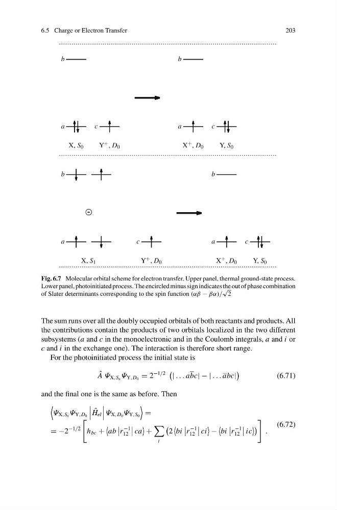
Fig. 6.7 Molecular orbital scheme for electron transfer. Upper panel, thermal ground-state process.
Lower panel, photoinitiated process. The encircled minus sign indicates the out of phase combination
of Slater determinants corresponding to the spin function (αβ − βα)/
√
2
The sum runs over all the doubly occupied orbitals of both reactants and products. All
the contributions contain the products of two orbitals localized in the two different
subsystems (a and c in the monoelectronic and in the Coulomb integrals, a and i or
c and i in the exchange one). The interaction is therefore short range.
For the photoinitiated process the initial state is
ˆ
A Ψ X,S n Ψ Y,D 0 = 2
−1/2
| . . . abc| − | . . . abc|
(6.71)
and the final one is the same as before. Then
Ψ X,S n Ψ Y,D 0
ˆ
H el
Ψ X,D 0 Ψ Y,S 0
=
= −2
−1/2
h bc +
ab
r
−1
12
ca
+
i
2
bi
r
−1
12
ci
−
bi
r
−1
12
ic
.
(6.72)
203
c
Y, S 0
b
a
X + , D 0
c
Y + , D 0
-
b
a
X, S 1
c
Y, S 0
b
a
X + , D 0
c
Y + , D 0
b
a
X, S 0
Fig. 6.7 Molecular orbital scheme for electron transfer. Upper panel, thermal ground-state process.
Lower panel, photoinitiated process. The encircled minus sign indicates the out of phase combination
of Slater determinants corresponding to the spin function (αβ − βα)/
√
2
The sum runs over all the doubly occupied orbitals of both reactants and products. All
the contributions contain the products of two orbitals localized in the two different
subsystems (a and c in the monoelectronic and in the Coulomb integrals, a and i or
c and i in the exchange one). The interaction is therefore short range.
For the photoinitiated process the initial state is
ˆ
A Ψ X,S n Ψ Y,D 0 = 2
−1/2
| . . . abc| − | . . . abc|
(6.71)
and the final one is the same as before. Then
Ψ X,S n Ψ Y,D 0
ˆ
H el
Ψ X,D 0 Ψ Y,S 0
=
= −2
−1/2
h bc +
ab
r
−1
12
ca
+
i
2
bi
r
−1
12
ci
−
bi
r
−1
12
ic
.
(6.72)