

98
6 Engineering Applications of Facility Layout
Wr1
Wr2
Wr3
I1
I2
I3
P
A1
A2
A3
Wp1
Wp2
Wp3
(100,100,200)
(1 0 0 ,3 0 0 ,3 0 0 )
( 5 0 0 , 6 0 0 , 6 0 0 )
(0 ,0 ,2 5 0 )
(250,250,250)
(100,100,200)
(1 50 ,1 50 ,0 )
(15 0,3 00, 300 )
( 3 5 0 , 3 5 0 , 3 5 0 )
(0,0,100)
( 0 ,1 0 0 ,1 0 0 )
(0 ,0 ,1 50 )
(15 0,1 50 ,15 0)
(1 00 ,1 00 ,0 )
( 5 0 ,5 0 ,2 0 0 )
(2 0 0 ,2 0 0 ,2 0 0 )
( 0 , 0 , 5 0 )
(0 ,5 0 ,5 0 )
(0 ,1 5 0 ,0 )
(350,350,0)
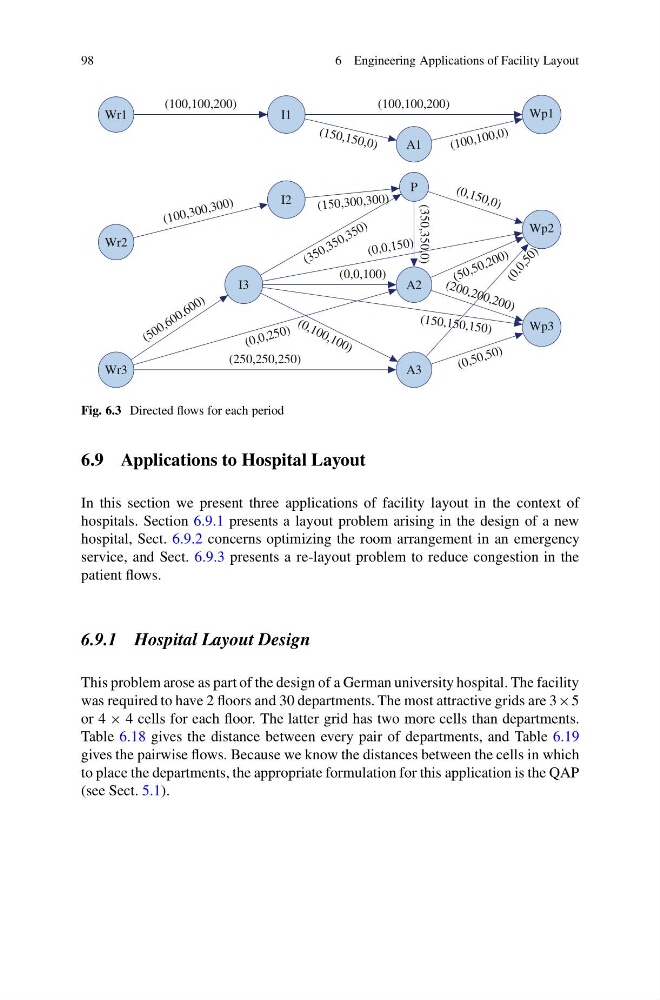
Fig. 6.3 Directed flows for each period
6.9 Applications to Hospital Layout
In this section we present three applications of facility layout in the context of
hospitals. Section 6.9.1 presents a layout problem arising in the design of a new
hospital, Sect. 6.9.2 concerns optimizing the room arrangement in an emergency
service, and Sect. 6.9.3 presents a re-layout problem to reduce congestion in the
patient flows.
6.9.1 Hospital Layout Design
This problem arose as part of the design of a German university hospital. The facility
was required to have 2 floors and 30 departments. The most attractive grids are 3×5
or 4 × 4 cells for each floor. The latter grid has two more cells than departments.
Table 6.18 gives the distance between every pair of departments, and Table 6.19
gives the pairwise flows. Because we know the distances between the cells in which
to place the departments, the appropriate formulation for this application is the QAP
(see Sect. 5.1).
6 Engineering Applications of Facility Layout
Wr1
Wr2
Wr3
I1
I2
I3
P
A1
A2
A3
Wp1
Wp2
Wp3
(100,100,200)
(1 0 0 ,3 0 0 ,3 0 0 )
( 5 0 0 , 6 0 0 , 6 0 0 )
(0 ,0 ,2 5 0 )
(250,250,250)
(100,100,200)
(1 50 ,1 50 ,0 )
(15 0,3 00, 300 )
( 3 5 0 , 3 5 0 , 3 5 0 )
(0,0,100)
( 0 ,1 0 0 ,1 0 0 )
(0 ,0 ,1 50 )
(15 0,1 50 ,15 0)
(1 00 ,1 00 ,0 )
( 5 0 ,5 0 ,2 0 0 )
(2 0 0 ,2 0 0 ,2 0 0 )
( 0 , 0 , 5 0 )
(0 ,5 0 ,5 0 )
(0 ,1 5 0 ,0 )
(350,350,0)
Fig. 6.3 Directed flows for each period
6.9 Applications to Hospital Layout
In this section we present three applications of facility layout in the context of
hospitals. Section 6.9.1 presents a layout problem arising in the design of a new
hospital, Sect. 6.9.2 concerns optimizing the room arrangement in an emergency
service, and Sect. 6.9.3 presents a re-layout problem to reduce congestion in the
patient flows.
6.9.1 Hospital Layout Design
This problem arose as part of the design of a German university hospital. The facility
was required to have 2 floors and 30 departments. The most attractive grids are 3×5
or 4 × 4 cells for each floor. The latter grid has two more cells than departments.
Table 6.18 gives the distance between every pair of departments, and Table 6.19
gives the pairwise flows. Because we know the distances between the cells in which
to place the departments, the appropriate formulation for this application is the QAP
(see Sect. 5.1).