

6 Diagnostic Capability of Optical Coherence Tomography …
135
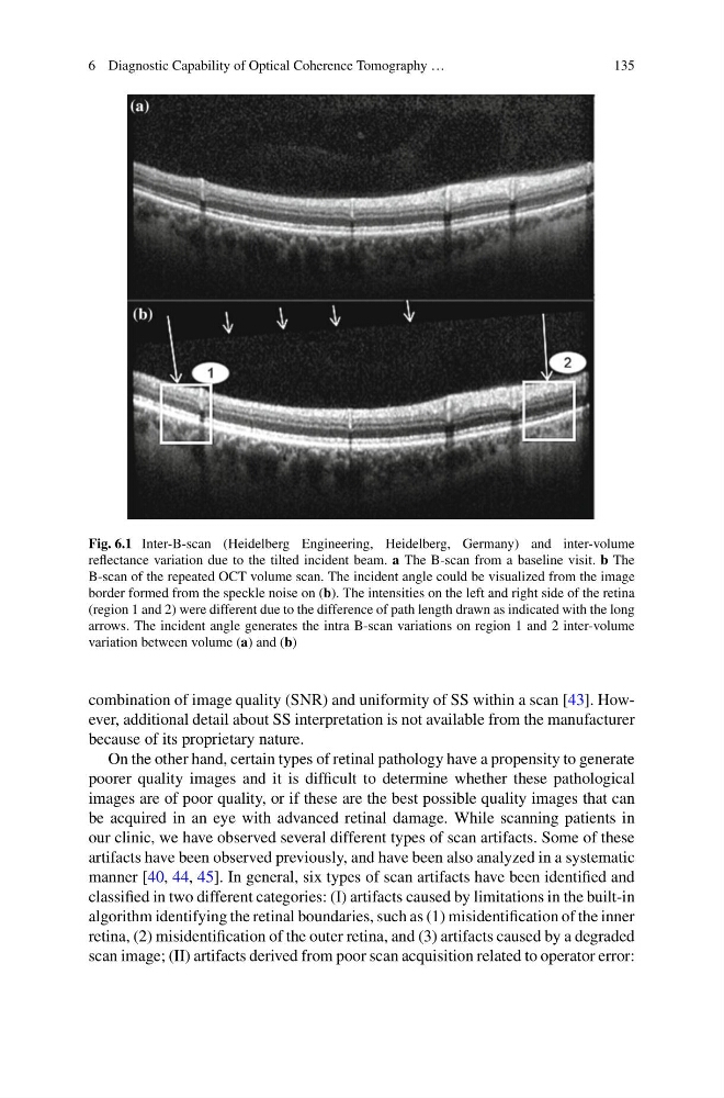
Fig. 6.1 Inter-B-scan (Heidelberg Engineering, Heidelberg, Germany) and inter-volume
reflectance variation due to the tilted incident beam. a The B-scan from a baseline visit. b The
B-scan of the repeated OCT volume scan. The incident angle could be visualized from the image
border formed from the speckle noise on (b). The intensities on the left and right side of the retina
(region 1 and 2) were different due to the difference of path length drawn as indicated with the long
arrows. The incident angle generates the intra B-scan variations on region 1 and 2 inter-volume
variation between volume (a) and (b)
combination of image quality (SNR) and uniformity of SS within a scan [43]. However, additional detail about SS interpretation is not available from the manufacturer
because of its proprietary nature.
On the other hand, certain types of retinal pathology have a propensity to generate
poorer quality images and it is difficult to determine whether these pathological
images are of poor quality, or if these are the best possible quality images that can
be acquired in an eye with advanced retinal damage. While scanning patients in
our clinic, we have observed several different types of scan artifacts. Some of these
artifacts have been observed previously, and have been also analyzed in a systematic
manner [40, 44, 45]. In general, six types of scan artifacts have been identified and
classified in two different categories: (I) artifacts caused by limitations in the built-in
algorithm identifying the retinal boundaries, such as (1) misidentification of the inner
retina, (2) misidentification of the outer retina, and (3) artifacts caused by a degraded
scan image; (II) artifacts derived from poor scan acquisition related to operator error:
135
Fig. 6.1 Inter-B-scan (Heidelberg Engineering, Heidelberg, Germany) and inter-volume
reflectance variation due to the tilted incident beam. a The B-scan from a baseline visit. b The
B-scan of the repeated OCT volume scan. The incident angle could be visualized from the image
border formed from the speckle noise on (b). The intensities on the left and right side of the retina
(region 1 and 2) were different due to the difference of path length drawn as indicated with the long
arrows. The incident angle generates the intra B-scan variations on region 1 and 2 inter-volume
variation between volume (a) and (b)
combination of image quality (SNR) and uniformity of SS within a scan [43]. However, additional detail about SS interpretation is not available from the manufacturer
because of its proprietary nature.
On the other hand, certain types of retinal pathology have a propensity to generate
poorer quality images and it is difficult to determine whether these pathological
images are of poor quality, or if these are the best possible quality images that can
be acquired in an eye with advanced retinal damage. While scanning patients in
our clinic, we have observed several different types of scan artifacts. Some of these
artifacts have been observed previously, and have been also analyzed in a systematic
manner [40, 44, 45]. In general, six types of scan artifacts have been identified and
classified in two different categories: (I) artifacts caused by limitations in the built-in
algorithm identifying the retinal boundaries, such as (1) misidentification of the inner
retina, (2) misidentification of the outer retina, and (3) artifacts caused by a degraded
scan image; (II) artifacts derived from poor scan acquisition related to operator error: