

20.4.3
•
•
•
Annual losses in grid-connected PV systems
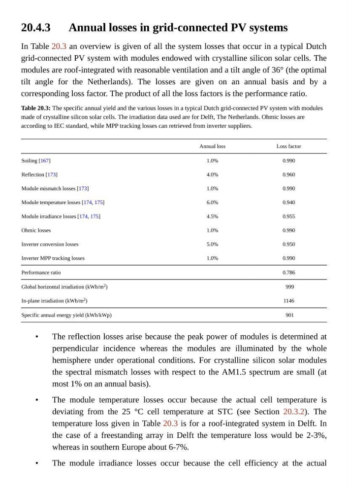
In Table 20.3 an overview is given of all the system losses that occur in a typical Dutch
grid-connected PV system with modules endowed with crystalline silicon solar cells. The
modules are roof-integrated with reasonable ventilation and a tilt angle of 36° (the optimal
tilt angle for the Netherlands). The losses are given on an annual basis and by a
corresponding loss factor. The product of all the loss factors is the performance ratio.
Table 20.3: The specific annual yield and the various losses in a typical Dutch grid-connected PV system with modules
made of crystalline silicon solar cells. The irradiation data used are for Delft, The Netherlands. Ohmic losses are
according to IEC standard, while MPP tracking losses can retrieved from inverter suppliers.
Annual loss
Loss factor
Soiling [167]
1.0%
0.990
Reflection [173]
4.0%
0.960
Module mismatch losses [173]
1.0%
0.990
Module temperature losses [174, 175]
6.0%
0.940
Module irradiance losses [174, 175]
4.5%
0.955
Ohmic losses
1.0%
0.990
Inverter conversion losses
5.0%
0.950
Inverter MPP tracking losses
1.0%
0.990
Performance ratio
0.786
Global horizontal irradiation (kWh/m 2 )
999
In-plane irradiation (kWh/m 2 )
1146
Specific annual energy yield (kWh/kWp)
901
The reflection losses arise because the peak power of modules is determined at
perpendicular incidence whereas the modules are illuminated by the whole
hemisphere under operational conditions. For crystalline silicon solar modules
the spectral mismatch losses with respect to the AM1.5 spectrum are small (at
most 1% on an annual basis).
The module temperature losses occur because the actual cell temperature is
deviating from the 25 °C cell temperature at STC (see Section 20.3.2). The
temperature loss given in Table 20.3 is for a roof-integrated system in Delft. In
the case of a freestanding array in Delft the temperature loss would be 2-3%,
whereas in southern Europe about 6-7%.
The module irradiance losses occur because the cell efficiency at the actual
•
•
•
Annual losses in grid-connected PV systems
In Table 20.3 an overview is given of all the system losses that occur in a typical Dutch
grid-connected PV system with modules endowed with crystalline silicon solar cells. The
modules are roof-integrated with reasonable ventilation and a tilt angle of 36° (the optimal
tilt angle for the Netherlands). The losses are given on an annual basis and by a
corresponding loss factor. The product of all the loss factors is the performance ratio.
Table 20.3: The specific annual yield and the various losses in a typical Dutch grid-connected PV system with modules
made of crystalline silicon solar cells. The irradiation data used are for Delft, The Netherlands. Ohmic losses are
according to IEC standard, while MPP tracking losses can retrieved from inverter suppliers.
Annual loss
Loss factor
Soiling [167]
1.0%
0.990
Reflection [173]
4.0%
0.960
Module mismatch losses [173]
1.0%
0.990
Module temperature losses [174, 175]
6.0%
0.940
Module irradiance losses [174, 175]
4.5%
0.955
Ohmic losses
1.0%
0.990
Inverter conversion losses
5.0%
0.950
Inverter MPP tracking losses
1.0%
0.990
Performance ratio
0.786
Global horizontal irradiation (kWh/m 2 )
999
In-plane irradiation (kWh/m 2 )
1146
Specific annual energy yield (kWh/kWp)
901
The reflection losses arise because the peak power of modules is determined at
perpendicular incidence whereas the modules are illuminated by the whole
hemisphere under operational conditions. For crystalline silicon solar modules
the spectral mismatch losses with respect to the AM1.5 spectrum are small (at
most 1% on an annual basis).
The module temperature losses occur because the actual cell temperature is
deviating from the 25 °C cell temperature at STC (see Section 20.3.2). The
temperature loss given in Table 20.3 is for a roof-integrated system in Delft. In
the case of a freestanding array in Delft the temperature loss would be 2-3%,
whereas in southern Europe about 6-7%.
The module irradiance losses occur because the cell efficiency at the actual