

where G M is the irradiance incident on the PV module, as introduced in Section 18.2. The
maximum variation of the FF for irradiance values between 1 and 1,000 W/m
2
is about
2% for CdTe, 5% for a-Si:H, 22% for poly crystalline silicon, and 23% for mono
crystalline silicon [166].
The short circuit current of a PV module is directly proportional to the irradiance,
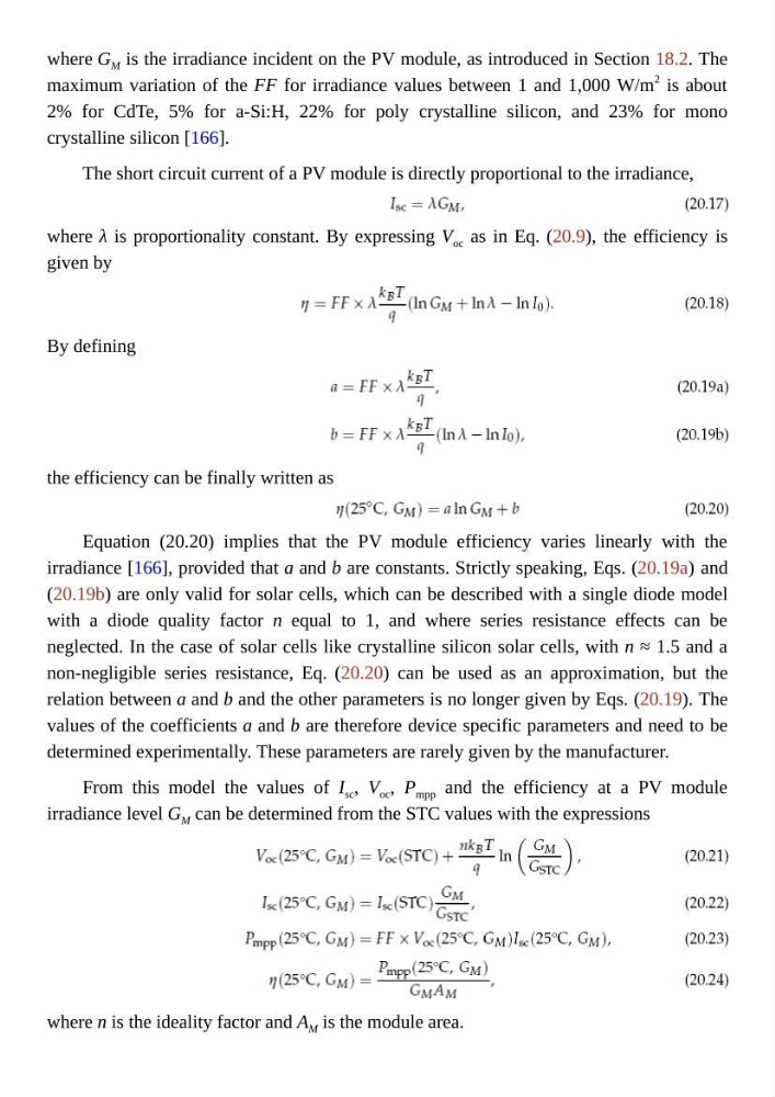
where λ is proportionality constant. By expressing V oc as in Eq. (20.9), the efficiency is
given by
By defining
the efficiency can be finally written as
Equation (20.20) implies that the PV module efficiency varies linearly with the
irradiance [166], provided that a and b are constants. Strictly speaking, Eqs. (20.19a) and
(20.19b) are only valid for solar cells, which can be described with a single diode model
with a diode quality factor n equal to 1, and where series resistance effects can be
neglected. In the case of solar cells like crystalline silicon solar cells, with n ≈ 1.5 and a
non-negligible series resistance, Eq. (20.20) can be used as an approximation, but the
relation between a and b and the other parameters is no longer given by Eqs. (20.19). The
values of the coefficients a and b are therefore device specific parameters and need to be
determined experimentally. These parameters are rarely given by the manufacturer.
From this model the values of I sc , V oc , P mpp and the efficiency at a PV module
irradiance level G M can be determined from the STC values with the expressions
where n is the ideality factor and A M is the module area.
maximum variation of the FF for irradiance values between 1 and 1,000 W/m
2
is about
2% for CdTe, 5% for a-Si:H, 22% for poly crystalline silicon, and 23% for mono
crystalline silicon [166].
The short circuit current of a PV module is directly proportional to the irradiance,
where λ is proportionality constant. By expressing V oc as in Eq. (20.9), the efficiency is
given by
By defining
the efficiency can be finally written as
Equation (20.20) implies that the PV module efficiency varies linearly with the
irradiance [166], provided that a and b are constants. Strictly speaking, Eqs. (20.19a) and
(20.19b) are only valid for solar cells, which can be described with a single diode model
with a diode quality factor n equal to 1, and where series resistance effects can be
neglected. In the case of solar cells like crystalline silicon solar cells, with n ≈ 1.5 and a
non-negligible series resistance, Eq. (20.20) can be used as an approximation, but the
relation between a and b and the other parameters is no longer given by Eqs. (20.19). The
values of the coefficients a and b are therefore device specific parameters and need to be
determined experimentally. These parameters are rarely given by the manufacturer.
From this model the values of I sc , V oc , P mpp and the efficiency at a PV module
irradiance level G M can be determined from the STC values with the expressions
where n is the ideality factor and A M is the module area.