

13.5
13.6
(a)
(b)
(c)
(d)
(e)
(f)
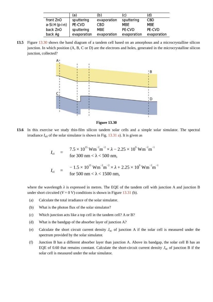
Figure 13.30 shows the band diagram of a tandem cell based on an amorphous and a microcrystalline silicon
junction. In which position (A, B, C or D) are the electrons and holes, generated in the microcrystalline silicon
junction, collected?
Figure 13.30
In this exercise we study thin-film silicon tandem solar cells and a simple solar simulator. The spectral
irradiance I eλ of the solar simulator is shown in Fig. 13.31 a). It is given as
I eλ =
7.5 × 10
15 Wm
−2
m
−2
× λ − 2.25 × 10
9 Wm
−2 m
−1
for 300 nm < λ < 500 nm,
I eλ =
− 1.5 × 10
15 Wm
−2
m
−2 × λ + 2.25 × 10
9 Wm
−2 m
−1
for 500 nm < λ < 1500 nm,
where the wavelength λ is expressed in metres. The EQE of the tandem cell with junction A and junction B
under short circuited (V = 0 V) conditions is shown in Figure 13.31 (b).
Calculate the total irradiance of the solar simulator.
What is the photon flux of the solar simulator?
Which junction acts like a top cell in the tandem cell? A or B?
What is the bandgap of the absorber layer of junction A?
Calculate the short circuit current density J sc of junction A if the solar cell is measured under the
spectrum provided by the solar simulator.
Junction B has a different absorber layer than junction A. Above its bandgap, the solar cell B has an
EQE of 0.60 that remains constant. Calculate the short-circuit current density J sc of junction B if the
solar cell is measured under the solar simulator.
13.6
(a)
(b)
(c)
(d)
(e)
(f)
Figure 13.30 shows the band diagram of a tandem cell based on an amorphous and a microcrystalline silicon
junction. In which position (A, B, C or D) are the electrons and holes, generated in the microcrystalline silicon
junction, collected?
Figure 13.30
In this exercise we study thin-film silicon tandem solar cells and a simple solar simulator. The spectral
irradiance I eλ of the solar simulator is shown in Fig. 13.31 a). It is given as
I eλ =
7.5 × 10
15 Wm
−2
m
−2
× λ − 2.25 × 10
9 Wm
−2 m
−1
for 300 nm < λ < 500 nm,
I eλ =
− 1.5 × 10
15 Wm
−2
m
−2 × λ + 2.25 × 10
9 Wm
−2 m
−1
for 500 nm < λ < 1500 nm,
where the wavelength λ is expressed in metres. The EQE of the tandem cell with junction A and junction B
under short circuited (V = 0 V) conditions is shown in Figure 13.31 (b).
Calculate the total irradiance of the solar simulator.
What is the photon flux of the solar simulator?
Which junction acts like a top cell in the tandem cell? A or B?
What is the bandgap of the absorber layer of junction A?
Calculate the short circuit current density J sc of junction A if the solar cell is measured under the
spectrum provided by the solar simulator.
Junction B has a different absorber layer than junction A. Above its bandgap, the solar cell B has an
EQE of 0.60 that remains constant. Calculate the short-circuit current density J sc of junction B if the
solar cell is measured under the solar simulator.