

through the material, but they have a low lifetime in organic materials, recombining back
to the ground state within a few nanoseconds. Hence, the diffusion length of such excitons
is in the order of only 10 nm.
If an electron donor and an electron acceptor material are brought together, an
interface is formed between those two. The HOMO and LUMO of both polymers can be
aligned considering their energy levels with reference to the vacuum level, as illustrated in
Fig. 13.25 b). At the interface we see a difference in the HOMO and LUMO levels.
Because of this difference, an electrostatic force exists between the two materials. If the
materials are chosen such that the difference is large enough, these local be injected into
the electron acceptor and a hole remains in the electron donor material .
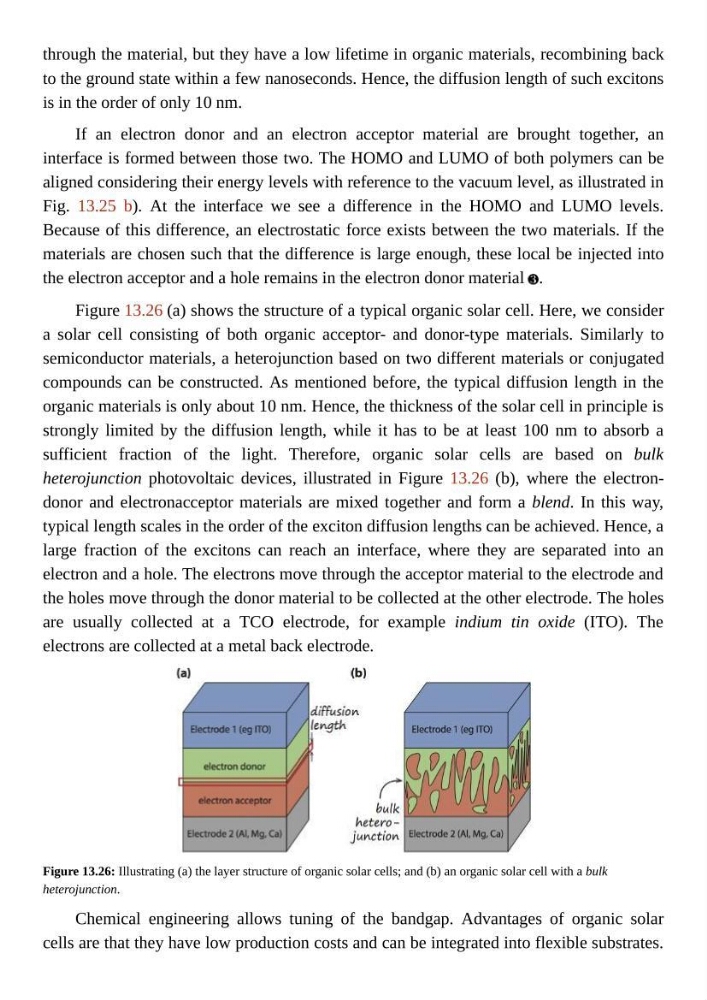
Figure 13.26 (a) shows the structure of a typical organic solar cell. Here, we consider
a solar cell consisting of both organic acceptor- and donor-type materials. Similarly to
semiconductor materials, a heterojunction based on two different materials or conjugated
compounds can be constructed. As mentioned before, the typical diffusion length in the
organic materials is only about 10 nm. Hence, the thickness of the solar cell in principle is
strongly limited by the diffusion length, while it has to be at least 100 nm to absorb a
sufficient fraction of the light. Therefore, organic solar cells are based on bulk
heterojunction photovoltaic devices, illustrated in Figure 13.26 (b), where the electrondonor and electronacceptor materials are mixed together and form a blend. In this way,
typical length scales in the order of the exciton diffusion lengths can be achieved. Hence, a
large fraction of the excitons can reach an interface, where they are separated into an
electron and a hole. The electrons move through the acceptor material to the electrode and
the holes move through the donor material to be collected at the other electrode. The holes
are usually collected at a TCO electrode, for example indium tin oxide (ITO). The
electrons are collected at a metal back electrode.
Figure 13.26: Illustrating (a) the layer structure of organic solar cells; and (b) an organic solar cell with a bulk
heterojunction.
Chemical engineering allows tuning of the bandgap. Advantages of organic solar
cells are that they have low production costs and can be integrated into flexible substrates.
to the ground state within a few nanoseconds. Hence, the diffusion length of such excitons
is in the order of only 10 nm.
If an electron donor and an electron acceptor material are brought together, an
interface is formed between those two. The HOMO and LUMO of both polymers can be
aligned considering their energy levels with reference to the vacuum level, as illustrated in
Fig. 13.25 b). At the interface we see a difference in the HOMO and LUMO levels.
Because of this difference, an electrostatic force exists between the two materials. If the
materials are chosen such that the difference is large enough, these local be injected into
the electron acceptor and a hole remains in the electron donor material .
Figure 13.26 (a) shows the structure of a typical organic solar cell. Here, we consider
a solar cell consisting of both organic acceptor- and donor-type materials. Similarly to
semiconductor materials, a heterojunction based on two different materials or conjugated
compounds can be constructed. As mentioned before, the typical diffusion length in the
organic materials is only about 10 nm. Hence, the thickness of the solar cell in principle is
strongly limited by the diffusion length, while it has to be at least 100 nm to absorb a
sufficient fraction of the light. Therefore, organic solar cells are based on bulk
heterojunction photovoltaic devices, illustrated in Figure 13.26 (b), where the electrondonor and electronacceptor materials are mixed together and form a blend. In this way,
typical length scales in the order of the exciton diffusion lengths can be achieved. Hence, a
large fraction of the excitons can reach an interface, where they are separated into an
electron and a hole. The electrons move through the acceptor material to the electrode and
the holes move through the donor material to be collected at the other electrode. The holes
are usually collected at a TCO electrode, for example indium tin oxide (ITO). The
electrons are collected at a metal back electrode.
Figure 13.26: Illustrating (a) the layer structure of organic solar cells; and (b) an organic solar cell with a bulk
heterojunction.
Chemical engineering allows tuning of the bandgap. Advantages of organic solar
cells are that they have low production costs and can be integrated into flexible substrates.