

9.3 The equivalent circuit
The J-V characteristic of an illuminated solar cell that behaves as the ideal diode is given
by Eq. (8.33),
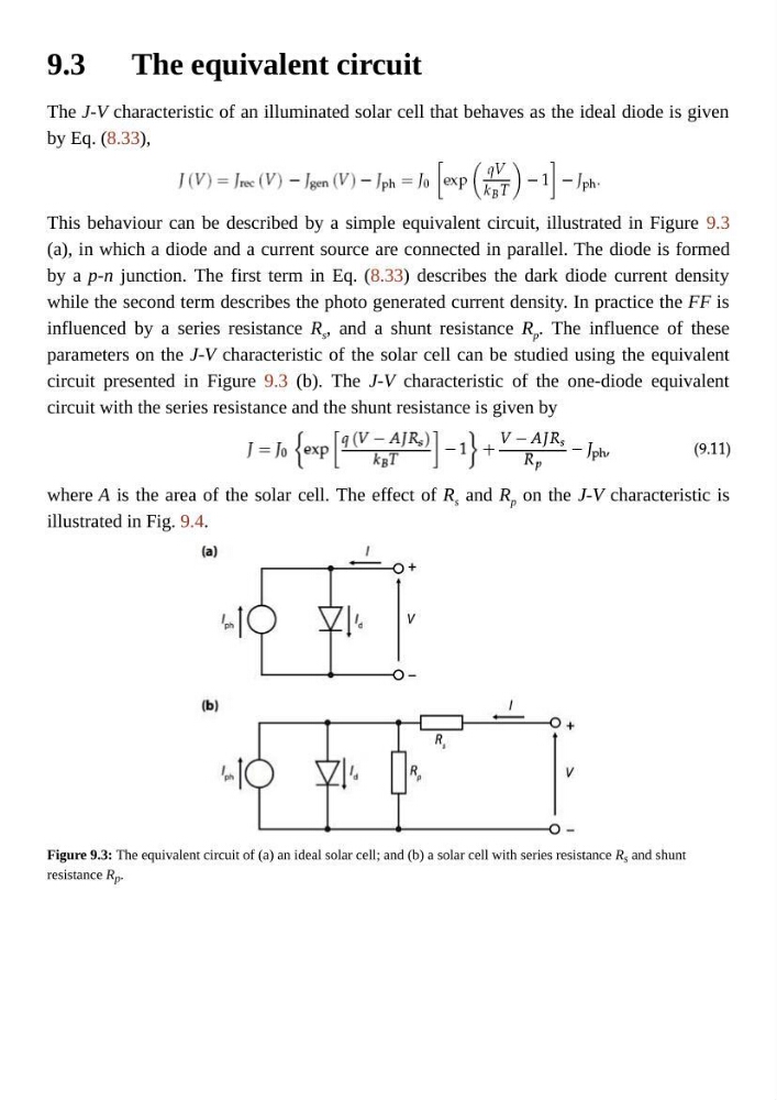
This behaviour can be described by a simple equivalent circuit, illustrated in Figure 9.3
(a), in which a diode and a current source are connected in parallel. The diode is formed
by a p-n junction. The first term in Eq. (8.33) describes the dark diode current density
while the second term describes the photo generated current density. In practice the FF is
influenced by a series resistance R s , and a shunt resistance R p . The influence of these
parameters on the J-V characteristic of the solar cell can be studied using the equivalent
circuit presented in Figure 9.3 (b). The J-V characteristic of the one-diode equivalent
circuit with the series resistance and the shunt resistance is given by
where A is the area of the solar cell. The effect of R s and R p on the J-V characteristic is
illustrated in Fig. 9.4.
Figure 9.3: The equivalent circuit of (a) an ideal solar cell; and (b) a solar cell with series resistance R s and shunt
resistance R p .
The J-V characteristic of an illuminated solar cell that behaves as the ideal diode is given
by Eq. (8.33),
This behaviour can be described by a simple equivalent circuit, illustrated in Figure 9.3
(a), in which a diode and a current source are connected in parallel. The diode is formed
by a p-n junction. The first term in Eq. (8.33) describes the dark diode current density
while the second term describes the photo generated current density. In practice the FF is
influenced by a series resistance R s , and a shunt resistance R p . The influence of these
parameters on the J-V characteristic of the solar cell can be studied using the equivalent
circuit presented in Figure 9.3 (b). The J-V characteristic of the one-diode equivalent
circuit with the series resistance and the shunt resistance is given by
where A is the area of the solar cell. The effect of R s and R p on the J-V characteristic is
illustrated in Fig. 9.4.
Figure 9.3: The equivalent circuit of (a) an ideal solar cell; and (b) a solar cell with series resistance R s and shunt
resistance R p .