

241
Constrained Autonomy
3
2
CPA (nm)
TCPA (min)
0.5
1
4
2
6
8
10
4
1
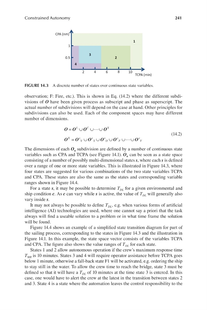
FIGURE 14.3 A discrete number of states over continuous state variables.
observation; F: Fire, etc.). This is shown in Eq. ( 14.2) where the different subdivisions of O have been given process as subscript and phase as superscript. The
actual number of subdivisions will depend on the case at hand. Other principles for
subdivisions can also be used. Each of the component spaces may have different
number of dimensions.
O O
=
∪
L
C
O
O
∪ ∪
X
(14.2)
O
O
X
x
=
∪O
O
x
∪
∪
x
O
O
x
∪ ∪
x
V
S
O
F
Y
The dimensions of each O n subdivision are defined by a number of continuous state
variables such as CPA and TCPA ( see Figure 14.1). O n can be seen as a state space
consisting of a number of possibly multi-dimensional states s, where each s is defined
over a range of one or more state variables. This is illustrated in F igure 14.3, where
four states are suggested for various combinations of the two state variables TCPA
and CPA. These states are also the same as the states and corresponding variable
ranges shown in Figure 14.4.
For a state s, it may be possible to determine T DL for a given environmental and
ship condition c. As c can vary while s is active, the value of T DL will generally also
vary inside s.
It may not always be possible to define T DL , e.g. when various forms of artificial
intelligence ( AI) technologies are used, where one cannot say a priori that the task
always will find a useable solution to a problem or in what time frame the solution
will be found.
Figure 14.4 shows an example of a simplified state transition diagram for part of
the sailing process, corresponding to the states in Figure 14.3 and the illustration in
F igure 14.1. In this example, the state space vector consists of the variables TCPA
and CPA. The figure also shows the value ranges of T DL for each state.
States 1 and 2 allow autonomous operation if the crew’s maximum response time
T MR is 10 minutes. States 3 and 4 will require operator assistance before TCPA goes
below 1 minute, otherwise a f all-back state F1 will be activated, e.g. ordering the ship
to stay still in the water. To allow the crew time to reach the bridge, state 3 must be
defined so that it will have a T DL of 10 minutes at the time state 3 is entered. In this
case, one would have to alert the crew at the latest in the transition between states 2
and 3. State 4 is a state where the automation leaves the control responsibility to the
Constrained Autonomy
3
2
CPA (nm)
TCPA (min)
0.5
1
4
2
6
8
10
4
1
FIGURE 14.3 A discrete number of states over continuous state variables.
observation; F: Fire, etc.). This is shown in Eq. ( 14.2) where the different subdivisions of O have been given process as subscript and phase as superscript. The
actual number of subdivisions will depend on the case at hand. Other principles for
subdivisions can also be used. Each of the component spaces may have different
number of dimensions.
O O
=
∪
L
C
O
O
∪ ∪
X
(14.2)
O
O
X
x
=
∪O
O
x
∪
∪
x
O
O
x
∪ ∪
x
V
S
O
F
Y
The dimensions of each O n subdivision are defined by a number of continuous state
variables such as CPA and TCPA ( see Figure 14.1). O n can be seen as a state space
consisting of a number of possibly multi-dimensional states s, where each s is defined
over a range of one or more state variables. This is illustrated in F igure 14.3, where
four states are suggested for various combinations of the two state variables TCPA
and CPA. These states are also the same as the states and corresponding variable
ranges shown in Figure 14.4.
For a state s, it may be possible to determine T DL for a given environmental and
ship condition c. As c can vary while s is active, the value of T DL will generally also
vary inside s.
It may not always be possible to define T DL , e.g. when various forms of artificial
intelligence ( AI) technologies are used, where one cannot say a priori that the task
always will find a useable solution to a problem or in what time frame the solution
will be found.
Figure 14.4 shows an example of a simplified state transition diagram for part of
the sailing process, corresponding to the states in Figure 14.3 and the illustration in
F igure 14.1. In this example, the state space vector consists of the variables TCPA
and CPA. The figure also shows the value ranges of T DL for each state.
States 1 and 2 allow autonomous operation if the crew’s maximum response time
T MR is 10 minutes. States 3 and 4 will require operator assistance before TCPA goes
below 1 minute, otherwise a f all-back state F1 will be activated, e.g. ordering the ship
to stay still in the water. To allow the crew time to reach the bridge, state 3 must be
defined so that it will have a T DL of 10 minutes at the time state 3 is entered. In this
case, one would have to alert the crew at the latest in the transition between states 2
and 3. State 4 is a state where the automation leaves the control responsibility to the