

240
Sensemaking in Safety Critical and Complex Situations
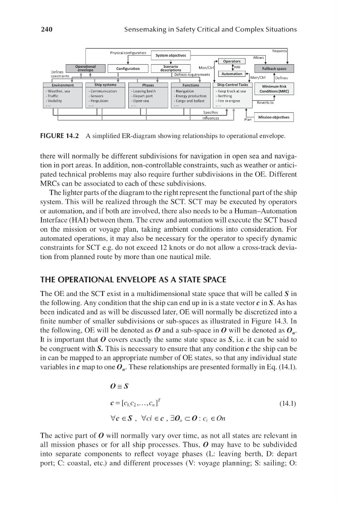
there will normally be different subdivisions for navigation in open sea and navigation in port areas. In addition, non-controllable constraints, such as weather or anticipated technical problems may also require further subdivisions in the OE. Different
MRCs can be associated to each of these subdivisions.
The lighter parts of the diagram to the right represent the functional part of the ship
system. This will be realized through the SCT. SCT may be executed by operators
or automation, and if both are involved, there also needs to be a Human–Automation
Interface ( HAI) between them. The crew and automation will execute the SCT based
on the mission or voyage plan, taking ambient conditions into consideration. For
automated operations, it may also be necessary for the operator to specify dynamic
constraints for SCT e.g. do not exceed 12 knots or do not allow a c ross-track deviation from planned route by more than one nautical mile.
THE OPERATIONAL ENVELOPE AS A STATE SPACE
The OE and the SCT exist in a multidimensional state space that will be called S in
the following. Any condition that the ship can end up in is a state vector c in S. As has
been indicated and as will be discussed later, OE will normally be discretized into a
finite number of smaller subdivisions or s ub-spaces as illustrated in F igure 14.3. In
the following, OE will be denoted as O and a s ub-space in O will be denoted as O n .
It is important that O covers exactly the same state space as S, i.e. it can be said to
be congruent with S. This is necessary to ensure that any condition c the ship can be
in can be mapped to an appropriate number of OE states, so that any individual state
variables in c map to one O n . These relationships are presented formally in Eq. ( 14.1).
O ≅ S
c =
…
[
,
c c
c
T
1, 2
, ]
n
(14.1)
∀ ∈
c S
, ∀ ∈
ci c O
, ∃ ⊂
n
i
O : c O
∈ n
The active part of O will normally vary over time, as not all states are relevant in
all mission phases or for all ship processes. Thus, O may have to be subdivided
into separate components to reflect voyage phases ( L: leaving berth, D: depart
port; C: coastal, etc.) and different processes ( V: voyage planning; S: sailing; O:
Operational
envelope
Ship Control Tasks
- Keep track at sea
- Berthing
- Fire in engine
- ···
Fallback space
Minimum Risk
Conditions (MRC)
Environment
- Weather, sea
- Traffic
- Visibility
- ···
Ship systems
- Communication
- Sensors
- Propulsion
- ···
Phases
- Leaving berth
- Depart port
- Open sea
- ···
Functions
- Navigation
- Energy production
- Cargo and ballast
- ···
System objectives
Operators
Automation
HAI
Mon/Ctrl
Specifies
Influences
Allows
Reverts to
Defines
constraints
Defines requirements
Requires
Configuration
Physical configuration
Mission objectives
Plan
Mon/Ctrl
Scenario
descriptions
Defines
FIGURE 14.2 A simplified ER-diagram showing relationships to operational envelope.
Sensemaking in Safety Critical and Complex Situations
there will normally be different subdivisions for navigation in open sea and navigation in port areas. In addition, non-controllable constraints, such as weather or anticipated technical problems may also require further subdivisions in the OE. Different
MRCs can be associated to each of these subdivisions.
The lighter parts of the diagram to the right represent the functional part of the ship
system. This will be realized through the SCT. SCT may be executed by operators
or automation, and if both are involved, there also needs to be a Human–Automation
Interface ( HAI) between them. The crew and automation will execute the SCT based
on the mission or voyage plan, taking ambient conditions into consideration. For
automated operations, it may also be necessary for the operator to specify dynamic
constraints for SCT e.g. do not exceed 12 knots or do not allow a c ross-track deviation from planned route by more than one nautical mile.
THE OPERATIONAL ENVELOPE AS A STATE SPACE
The OE and the SCT exist in a multidimensional state space that will be called S in
the following. Any condition that the ship can end up in is a state vector c in S. As has
been indicated and as will be discussed later, OE will normally be discretized into a
finite number of smaller subdivisions or s ub-spaces as illustrated in F igure 14.3. In
the following, OE will be denoted as O and a s ub-space in O will be denoted as O n .
It is important that O covers exactly the same state space as S, i.e. it can be said to
be congruent with S. This is necessary to ensure that any condition c the ship can be
in can be mapped to an appropriate number of OE states, so that any individual state
variables in c map to one O n . These relationships are presented formally in Eq. ( 14.1).
O ≅ S
c =
…
[
,
c c
c
T
1, 2
, ]
n
(14.1)
∀ ∈
c S
, ∀ ∈
ci c O
, ∃ ⊂
n
i
O : c O
∈ n
The active part of O will normally vary over time, as not all states are relevant in
all mission phases or for all ship processes. Thus, O may have to be subdivided
into separate components to reflect voyage phases ( L: leaving berth, D: depart
port; C: coastal, etc.) and different processes ( V: voyage planning; S: sailing; O:
Operational
envelope
Ship Control Tasks
- Keep track at sea
- Berthing
- Fire in engine
- ···
Fallback space
Minimum Risk
Conditions (MRC)
Environment
- Weather, sea
- Traffic
- Visibility
- ···
Ship systems
- Communication
- Sensors
- Propulsion
- ···
Phases
- Leaving berth
- Depart port
- Open sea
- ···
Functions
- Navigation
- Energy production
- Cargo and ballast
- ···
System objectives
Operators
Automation
HAI
Mon/Ctrl
Specifies
Influences
Allows
Reverts to
Defines
constraints
Defines requirements
Requires
Configuration
Physical configuration
Mission objectives
Plan
Mon/Ctrl
Scenario
descriptions
Defines
FIGURE 14.2 A simplified ER-diagram showing relationships to operational envelope.