

514
The Chemistry and Technology of Petroleum
with hydrogen in the presence of a catalyst. Reforming causes a rearrangement of the structures of
the molecular constituents and creates a gasoline product.
Catalytic cracking has a number of advantages over thermal cracking (Table 19.2; see
also Avidan and Shinnar, 1990; Avidan et al., 1990). Gasoline produced by catalytic cracking has a higher octane number and consists largely of iso-paraffins and aromatics. The isoparaffins and aromatic hydrocarbons have high octane numbers and greater chemical stability
than mono- olefins (R–CH=CH 2 or R–CH=CH–R′) and diolefins (R–CH=CH–CH=CH 2 or
R–CH=CH(CH 2 ) n CH=CH=R′). The olefins and diolefins are present in much greater quantities
in gasoline produced by thermal cracking processes. Furthermore, substantial quantities of olefin
gases and smaller quantities of methane (CH 4 ), ethane (CH 3 CH 3 ), and ethylene (CH 2 =CH 2 ) are
produced by catalytic cracking. The olefin gases are suitable for polymer gasoline manufacture
(Chapters 24 and 26).
Sulfur compounds are changed in such a way that the sulfur content of gasoline produced by
catalytic cracking gasoline is lower than the sulfur content of gasoline produced by thermal cracking. Catalytic cracking produces less residuum and more of the useful gas oil constituents than
thermal cracking. Finally, the process has considerable flexibility, permitting the manufacture of
both motor gasoline and aviation gasoline and a variation in the gas oil production to meet changes
in the fuel oil market (Speight, 1986).
The feedstocks for catalytic cracking can be any one (or blends) of the following: (1) straightrun gas oil, (2) vacuum gas oil, (3) atmospheric residuum, and (4) vacuum residuum. If blends of
the above feedstocks are employed, compatibility of the constituents of the blends must be assured
under read to conditions or excessive coke will be laid down on to the catalyst. In addition, there
are several pretreatment options for the feedstocks for catalytic cracking units and these are (1) deasphalting to prevent excessive coking on catalyst surfaces, (2) demetallation, that is, the removal of
nickel, vanadium, and iron to prevent catalyst deactivation, (3) use of a short residence time as a
means of preparing the feedstock, and (4) hydrotreating or mild hydrocracking to prevent excessive
coking in the fluid catalytic cracking unit (Bartholic, 1981a,b; Marafi and Stanislaus, 1997; Speight,
2000, 2004; Speight and Ozum, 2002).
In addition, the goal is to reduce the sulfur content of the naphtha, and a number of process
options are available for reducing the sulfur content in fluid catalytic cracker naphtha, and the two
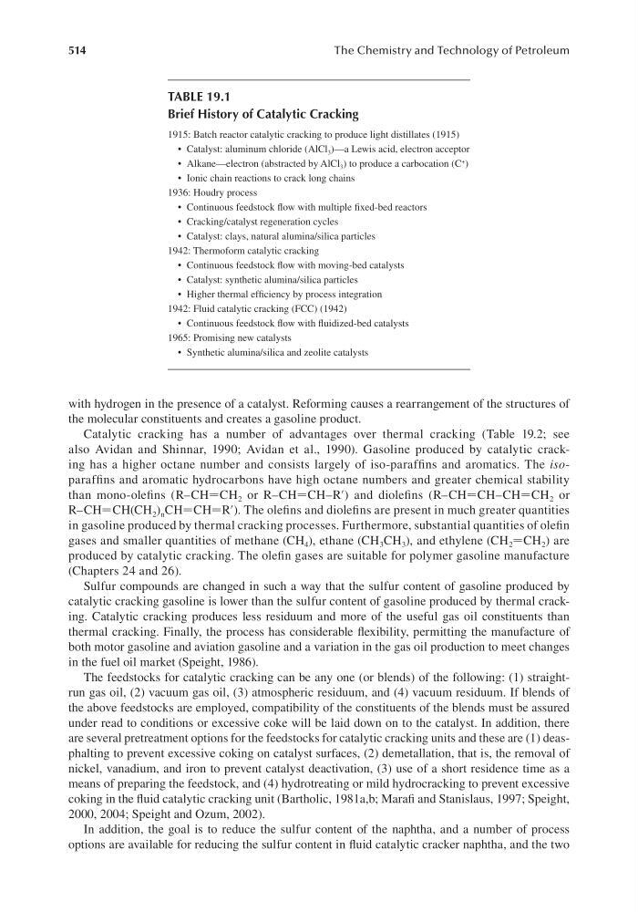
TABLE 19.1
Brief History of Catalytic Cracking
1915: Batch reactor catalytic cracking to produce light distillates (1915)
• Catalyst: aluminum chloride (AlCl 3 )—a Lewis acid, electron acceptor
• Alkane—electron (abstracted by AlCl 3 ) to produce a carbocation (C + )
• Ionic chain reactions to crack long chains
1936: Houdry process
• Continuous feedstock flow with multiple fixed-bed reactors
• Cracking/catalyst regeneration cycles
• Catalyst: clays, natural alumina/silica particles
1942: Thermoform catalytic cracking
• Continuous feedstock flow with moving-bed catalysts
• Catalyst: synthetic alumina/silica particles
• Higher thermal efficiency by process integration
1942: Fluid catalytic cracking (FCC) (1942)
• Continuous feedstock flow with fluidized-bed catalysts
1965: Promising new catalysts
• Synthetic alumina/silica and zeolite catalysts