

34 Beam-based Correction and Optimization for Accelerators
∆x (mm)
-2
0
2
s (m)
0
50
100
150
200
∆y (mm)
-2
0
2
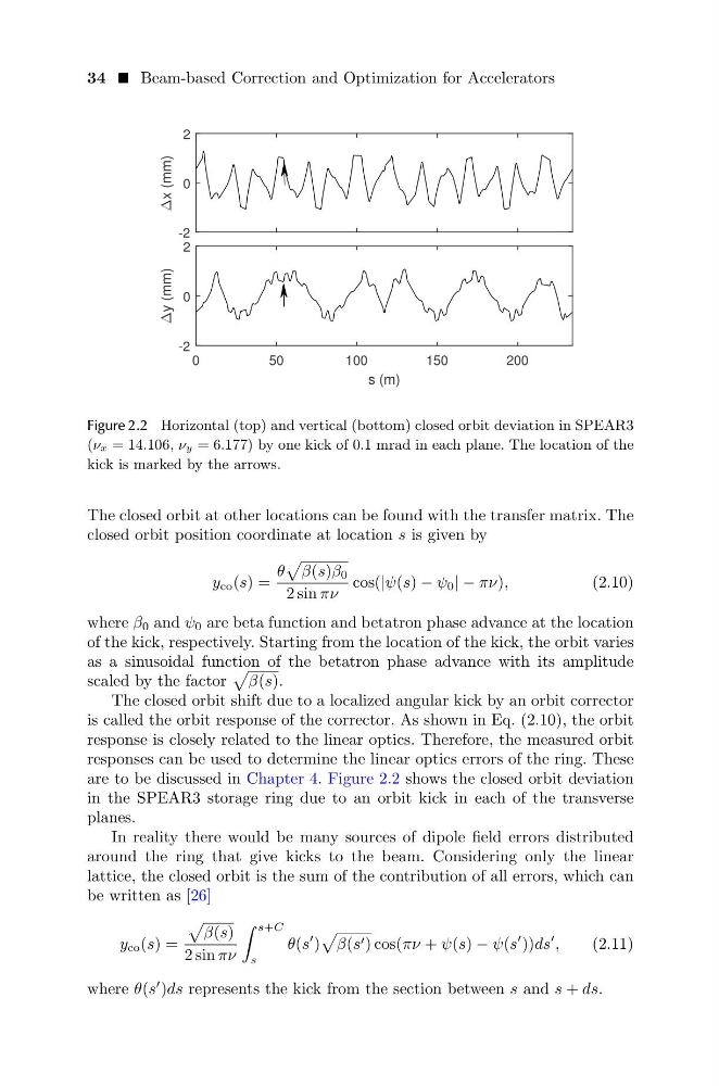
Figure 2.2 Horizontal (top) and vertical (bottom) closed orbit deviation in SPEAR3
(νx = 14.106, νy = 6.177) by one kick of 0.1 mrad in each plane. The location of the
kick is marked by the arrows.
The closed orbit at other locations can be found with the transfer matrix. The
closed orbit position coordinate at location s is given by
y co (s) =
θ
β(s)β 0
2 sin πν
cos(|ψ(s) − ψ 0 | − πν),
(2.10)
where β 0 and ψ 0 are beta function and betatron phase advance at the location
of the kick, respectively. Starting from the location of the kick, the orbit varies
as a sinusoidal function of the betatron phase advance with its amplitude
scaled by the factor
β(s).
The closed orbit shift due to a localized angular kick by an orbit corrector
is called the orbit response of the corrector. As shown in Eq. (2.10), the orbit
response is closely related to the linear optics. Therefore, the measured orbit
responses can be used to determine the linear optics errors of the ring. These
are to be discussed in Chapter 4. Figure 2.2 shows the closed orbit deviation
in the SPEAR3 storage ring due to an orbit kick in each of the transverse
planes.
In reality there would be many sources of dipole field errors distributed
around the ring that give kicks to the beam. Considering only the linear
lattice, the closed orbit is the sum of the contribution of all errors, which can
be written as [26]
y co (s) =
β(s)
2 sin πν
s+C
s
θ(s
)
β(s ) cos(πν + ψ(s) − ψ(s
))ds
,
(2.11)
where θ(s
)ds represents the kick from the section between s and s + ds.
∆x (mm)
-2
0
2
s (m)
0
50
100
150
200
∆y (mm)
-2
0
2
Figure 2.2 Horizontal (top) and vertical (bottom) closed orbit deviation in SPEAR3
(νx = 14.106, νy = 6.177) by one kick of 0.1 mrad in each plane. The location of the
kick is marked by the arrows.
The closed orbit at other locations can be found with the transfer matrix. The
closed orbit position coordinate at location s is given by
y co (s) =
θ
β(s)β 0
2 sin πν
cos(|ψ(s) − ψ 0 | − πν),
(2.10)
where β 0 and ψ 0 are beta function and betatron phase advance at the location
of the kick, respectively. Starting from the location of the kick, the orbit varies
as a sinusoidal function of the betatron phase advance with its amplitude
scaled by the factor
β(s).
The closed orbit shift due to a localized angular kick by an orbit corrector
is called the orbit response of the corrector. As shown in Eq. (2.10), the orbit
response is closely related to the linear optics. Therefore, the measured orbit
responses can be used to determine the linear optics errors of the ring. These
are to be discussed in Chapter 4. Figure 2.2 shows the closed orbit deviation
in the SPEAR3 storage ring due to an orbit kick in each of the transverse
planes.
In reality there would be many sources of dipole field errors distributed
around the ring that give kicks to the beam. Considering only the linear
lattice, the closed orbit is the sum of the contribution of all errors, which can
be written as [26]
y co (s) =
β(s)
2 sin πν
s+C
s
θ(s
)
β(s ) cos(πν + ψ(s) − ψ(s
))ds
,
(2.11)
where θ(s
)ds represents the kick from the section between s and s + ds.