

32 Beam-based Correction and Optimization for Accelerators
actual beam orbit to deviate from the design. Correction of orbit errors is a
basic requirement in accelerator operation.
Magnet misalignment introduces unintended multipole field components
on the beam through the so-called “feed-down” effects. Quadrupole and sextupole magnets are typically placed to have the magnetic axes on the design
orbit, such that a particle traveling on the design orbit sees no magnetic field.
When the magnet centers are shifted transversely to (−x 0 , −y 0 ), so that the
point (x, y) has coordinates relative to the magnet center
X = x 0 + x,
Y = y 0 + y,
the magnetic fields in a quadrupole at the point will be
B y = b 1 X = b 1 x 0 + b 1 x, B x = b 1 Y = b 1 y 0 + b 1 y,
(2.1)
and similarly the field in a sextupole will be
B y =
b 2
2
(x
2
0 − y
2
0 ) + (2x 0 x − 2y 0 y) + (x
2 − y
2 )
,
(2.2)
B x = b 2 (x 0 y 0 + xy 0 + x 0 y + xy).
(2.3)
The constant terms (independent of x and y) in the B y and B x are dipole
field errors. Dipole field errors give the beam angular kicks (i.e., changes to x
and y
coordinates),
θ x =
B y ∆s
Bρ
,
θ y = −
B x ∆s
Bρ
,
(2.4)
where ∆s is length of the field error. The angular kicks propagate downstream
and alter the beam orbit.
In a one-pass system (linac or transport line), the beam orbit change due
to a kick is calculated with the transfer matrix between the kick and the
observation points. Initial orbit errors at the entrance point of the line will
also propagate through the transfer matrix. The overall orbit error at any
location, P , can be obtained by summing up contributions from all upstream
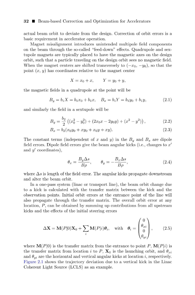
kicks and the effects of the initial steering errors
∆X = M(P |0)X 0 +
i
M(P |i)θ i , with θ i =
0
θ xi
0
θ yi
,
(2.5)
where M(P |0) is the transfer matrix from the entrance to point P , M(P |i) is
the transfer matrix from location i to P , X 0 is the launching orbit, and θ xi
and θ yi are the horizontal and vertical angular kicks at location i, respectively.
Figure 2.1 shows the trajectory deviation due to a vertical kick in the Linac
Coherent Light Source (LCLS) as an example.
actual beam orbit to deviate from the design. Correction of orbit errors is a
basic requirement in accelerator operation.
Magnet misalignment introduces unintended multipole field components
on the beam through the so-called “feed-down” effects. Quadrupole and sextupole magnets are typically placed to have the magnetic axes on the design
orbit, such that a particle traveling on the design orbit sees no magnetic field.
When the magnet centers are shifted transversely to (−x 0 , −y 0 ), so that the
point (x, y) has coordinates relative to the magnet center
X = x 0 + x,
Y = y 0 + y,
the magnetic fields in a quadrupole at the point will be
B y = b 1 X = b 1 x 0 + b 1 x, B x = b 1 Y = b 1 y 0 + b 1 y,
(2.1)
and similarly the field in a sextupole will be
B y =
b 2
2
(x
2
0 − y
2
0 ) + (2x 0 x − 2y 0 y) + (x
2 − y
2 )
,
(2.2)
B x = b 2 (x 0 y 0 + xy 0 + x 0 y + xy).
(2.3)
The constant terms (independent of x and y) in the B y and B x are dipole
field errors. Dipole field errors give the beam angular kicks (i.e., changes to x
and y
coordinates),
θ x =
B y ∆s
Bρ
,
θ y = −
B x ∆s
Bρ
,
(2.4)
where ∆s is length of the field error. The angular kicks propagate downstream
and alter the beam orbit.
In a one-pass system (linac or transport line), the beam orbit change due
to a kick is calculated with the transfer matrix between the kick and the
observation points. Initial orbit errors at the entrance point of the line will
also propagate through the transfer matrix. The overall orbit error at any
location, P , can be obtained by summing up contributions from all upstream
kicks and the effects of the initial steering errors
∆X = M(P |0)X 0 +
i
M(P |i)θ i , with θ i =
0
θ xi
0
θ yi
,
(2.5)
where M(P |0) is the transfer matrix from the entrance to point P , M(P |i) is
the transfer matrix from location i to P , X 0 is the launching orbit, and θ xi
and θ yi are the horizontal and vertical angular kicks at location i, respectively.
Figure 2.1 shows the trajectory deviation due to a vertical kick in the Linac
Coherent Light Source (LCLS) as an example.