

224 Beam-based Correction and Optimization for Accelerators
0
50
100
injection eff. (%)
85% kicker bump
77% kicker bump
0
50
100
150
200
evaluation
100
150
200
current (A)
SF2
SF3
SD2
SD3
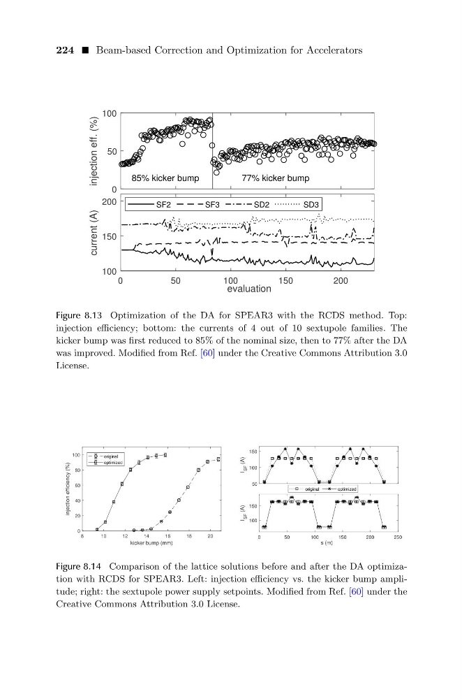
Figure 8.13 Optimization of the DA for SPEAR3 with the RCDS method. Top:
injection efficiency; bottom: the currents of 4 out of 10 sextupole families. The
kicker bump was first reduced to 85% of the nominal size, then to 77% after the DA
was improved. Modified from Ref. [60] under the Creative Commons Attribution 3.0
License.
8
10
12
14
16
18
20
kicker bump (mm)
0
20
40
60
80
100
injection efficiency (%)
original
optimized
50
100
150
I
SF
(A)
0
50
100
150
200
250
s (m)
100
150
I
SF
(A)
original
optimized
Figure 8.14 Comparison of the lattice solutions before and after the DA optimization with RCDS for SPEAR3. Left: injection efficiency vs. the kicker bump amplitude; right: the sextupole power supply setpoints. Modified from Ref. [60] under the
Creative Commons Attribution 3.0 License.
0
50
100
injection eff. (%)
85% kicker bump
77% kicker bump
0
50
100
150
200
evaluation
100
150
200
current (A)
SF2
SF3
SD2
SD3
Figure 8.13 Optimization of the DA for SPEAR3 with the RCDS method. Top:
injection efficiency; bottom: the currents of 4 out of 10 sextupole families. The
kicker bump was first reduced to 85% of the nominal size, then to 77% after the DA
was improved. Modified from Ref. [60] under the Creative Commons Attribution 3.0
License.
8
10
12
14
16
18
20
kicker bump (mm)
0
20
40
60
80
100
injection efficiency (%)
original
optimized
50
100
150
I
SF
(A)
0
50
100
150
200
250
s (m)
100
150
I
SF
(A)
original
optimized
Figure 8.14 Comparison of the lattice solutions before and after the DA optimization with RCDS for SPEAR3. Left: injection efficiency vs. the kicker bump amplitude; right: the sextupole power supply setpoints. Modified from Ref. [60] under the
Creative Commons Attribution 3.0 License.