

Coupling and nonlinear dynamics correction 165
zontal phase advance between the sextupole and the observation point. The
phase of the complex RDT coefficient changes with location in the ring but its
amplitude does not change except at the locations of the multipole magnets
that drive the resonance. Across a multipole magnet, the RDT coefficient has
a step change as the contribution from the multipole magnet changes phase.
If the RDTs can be measured before and after the multipole magnet, the
strength of the magnet could be determined directly.
In reality, there are not so many observation points to directly measure
the strengths of all multipole magnets. However, the connections between the
RDTs and the multipole magnets provide a way to resolve the multipole errors.
This can be done by fitting the measured RDTs to the lattice model. Other
observed features of the nonlinear dynamics can also be included. In general,
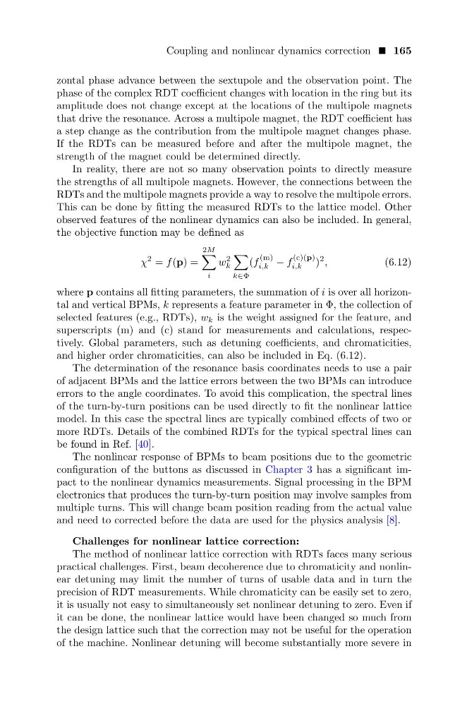
the objective function may be defined as
χ
2 = f (p) =
2M
i
w
2
k
k∈Φ
(f
(m)
i,k − f
(c)(p)
i,k
)
2 ,
(6.12)
where p contains all fitting parameters, the summation of i is over all horizontal and vertical BPMs, k represents a feature parameter in Φ, the collection of
selected features (e.g., RDTs), w k is the weight assigned for the feature, and
superscripts (m) and (c) stand for measurements and calculations, respectively. Global parameters, such as detuning coefficients, and chromaticities,
and higher order chromaticities, can also be included in Eq. (6.12).
The determination of the resonance basis coordinates needs to use a pair
of adjacent BPMs and the lattice errors between the two BPMs can introduce
errors to the angle coordinates. To avoid this complication, the spectral lines
of the turn-by-turn positions can be used directly to fit the nonlinear lattice
model. In this case the spectral lines are typically combined effects of two or
more RDTs. Details of the combined RDTs for the typical spectral lines can
be found in Ref. [40].
The nonlinear response of BPMs to beam positions due to the geometric
configuration of the buttons as discussed in Chapter 3 has a significant impact to the nonlinear dynamics measurements. Signal processing in the BPM
electronics that produces the turn-by-turn position may involve samples from
multiple turns. This will change beam position reading from the actual value
and need to corrected before the data are used for the physics analysis [8].
Challenges for nonlinear lattice correction:
The method of nonlinear lattice correction with RDTs faces many serious
practical challenges. First, beam decoherence due to chromaticity and nonlinear detuning may limit the number of turns of usable data and in turn the
precision of RDT measurements. While chromaticity can be easily set to zero,
it is usually not easy to simultaneously set nonlinear detuning to zero. Even if
it can be done, the nonlinear lattice would have been changed so much from
the design lattice such that the correction may not be useful for the operation
of the machine. Nonlinear detuning will become substantially more severe in
zontal phase advance between the sextupole and the observation point. The
phase of the complex RDT coefficient changes with location in the ring but its
amplitude does not change except at the locations of the multipole magnets
that drive the resonance. Across a multipole magnet, the RDT coefficient has
a step change as the contribution from the multipole magnet changes phase.
If the RDTs can be measured before and after the multipole magnet, the
strength of the magnet could be determined directly.
In reality, there are not so many observation points to directly measure
the strengths of all multipole magnets. However, the connections between the
RDTs and the multipole magnets provide a way to resolve the multipole errors.
This can be done by fitting the measured RDTs to the lattice model. Other
observed features of the nonlinear dynamics can also be included. In general,
the objective function may be defined as
χ
2 = f (p) =
2M
i
w
2
k
k∈Φ
(f
(m)
i,k − f
(c)(p)
i,k
)
2 ,
(6.12)
where p contains all fitting parameters, the summation of i is over all horizontal and vertical BPMs, k represents a feature parameter in Φ, the collection of
selected features (e.g., RDTs), w k is the weight assigned for the feature, and
superscripts (m) and (c) stand for measurements and calculations, respectively. Global parameters, such as detuning coefficients, and chromaticities,
and higher order chromaticities, can also be included in Eq. (6.12).
The determination of the resonance basis coordinates needs to use a pair
of adjacent BPMs and the lattice errors between the two BPMs can introduce
errors to the angle coordinates. To avoid this complication, the spectral lines
of the turn-by-turn positions can be used directly to fit the nonlinear lattice
model. In this case the spectral lines are typically combined effects of two or
more RDTs. Details of the combined RDTs for the typical spectral lines can
be found in Ref. [40].
The nonlinear response of BPMs to beam positions due to the geometric
configuration of the buttons as discussed in Chapter 3 has a significant impact to the nonlinear dynamics measurements. Signal processing in the BPM
electronics that produces the turn-by-turn position may involve samples from
multiple turns. This will change beam position reading from the actual value
and need to corrected before the data are used for the physics analysis [8].
Challenges for nonlinear lattice correction:
The method of nonlinear lattice correction with RDTs faces many serious
practical challenges. First, beam decoherence due to chromaticity and nonlinear detuning may limit the number of turns of usable data and in turn the
precision of RDT measurements. While chromaticity can be easily set to zero,
it is usually not easy to simultaneously set nonlinear detuning to zero. Even if
it can be done, the nonlinear lattice would have been changed so much from
the design lattice such that the correction may not be useful for the operation
of the machine. Nonlinear detuning will become substantially more severe in