

100 Beam-based Correction and Optimization for Accelerators
Typically, a BPM measures the horizontal and vertical beam positions simultaneously. Suppose there are M BPMs, N x horizontal correctors, and N y vertical correctors, the dimension of R xx and R yx is M × N x and the dimension
of R xy and R yy is M × N y . The dimension of R is thus 2M × (N x + N y ).
The orbit response of an orbit corrector is measured on the machine by
stepping the strength of the corrector and measuring the orbit shift. Because
of the presence of nonlinear magnets in the lattice, the orbit response is nonlinear to some extent. The impact of the nonlinearity to the accuracy of the
orbit response matrix can be minimized by using the bipolar scheme in the
measurement, in which the corrector strength is changed in both the negative
and positive directions by the same step size, ∆θ. The orbit responses are
then calculated with
R x =
x + − x −
2∆θ
, R y =
y + − y −
2∆θ
,
(4.15)
where subscripts + and − indicate the orbits for the positive and negative
steps, respectively. The step size of the corrector change is preferred to be
small in order to reduce the impact of the nonlinearity. On the other hand, a
large orbit shift relative to the BPM noise is desired for high data precision.
A good trade-off between the two conflicting requirements may depend on the
specific machine. Corrector step changes that causes orbit shifts of 1-2 mm
are usually a reasonable choice for a typical third generation light source.
In the measurement of the orbit response matrix, orbit correctors are used
to change the beam orbit and the BPMs are used to detect the orbit changes.
In reality, the correctors and BPMs can both have calibration errors. They
could also have rotations about the s-axis. These errors will cause the measured orbit response matrix to differ from the actual response matrix and
hence need to be accounted for. The actual kicks by a corrector are related to
the apparent kick values by
θ x
θ y
=
cos φ sin φ
− sin φ cos φ
k x ˜
θ x
k y ˜
θ y
,
(4.16)
where k x,y are the horizontal and vertical gains of the corrector kicks, φ is
the rotation about the s-axis, and ˜
θ and θ represent the actual and apparent
kicks, respectively.
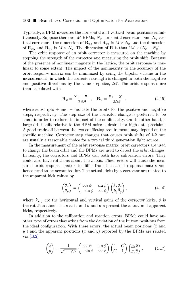
In addition to the calibration and rotation errors, BPMs could have another type of errors that arises from the deviation of the button positions from
the ideal configuration. With these errors, the actual beam positions (˜ x and
˜
y ) and the apparent positions (x and y) reported by the BPMs are related
via [102]
x
y
=
1
√
1 − C 2
cos φ sin φ
− sin φ cos φ
1 C
C 1
g x ˜
x
g y ˜
y
,
(4.17)
Typically, a BPM measures the horizontal and vertical beam positions simultaneously. Suppose there are M BPMs, N x horizontal correctors, and N y vertical correctors, the dimension of R xx and R yx is M × N x and the dimension
of R xy and R yy is M × N y . The dimension of R is thus 2M × (N x + N y ).
The orbit response of an orbit corrector is measured on the machine by
stepping the strength of the corrector and measuring the orbit shift. Because
of the presence of nonlinear magnets in the lattice, the orbit response is nonlinear to some extent. The impact of the nonlinearity to the accuracy of the
orbit response matrix can be minimized by using the bipolar scheme in the
measurement, in which the corrector strength is changed in both the negative
and positive directions by the same step size, ∆θ. The orbit responses are
then calculated with
R x =
x + − x −
2∆θ
, R y =
y + − y −
2∆θ
,
(4.15)
where subscripts + and − indicate the orbits for the positive and negative
steps, respectively. The step size of the corrector change is preferred to be
small in order to reduce the impact of the nonlinearity. On the other hand, a
large orbit shift relative to the BPM noise is desired for high data precision.
A good trade-off between the two conflicting requirements may depend on the
specific machine. Corrector step changes that causes orbit shifts of 1-2 mm
are usually a reasonable choice for a typical third generation light source.
In the measurement of the orbit response matrix, orbit correctors are used
to change the beam orbit and the BPMs are used to detect the orbit changes.
In reality, the correctors and BPMs can both have calibration errors. They
could also have rotations about the s-axis. These errors will cause the measured orbit response matrix to differ from the actual response matrix and
hence need to be accounted for. The actual kicks by a corrector are related to
the apparent kick values by
θ x
θ y
=
cos φ sin φ
− sin φ cos φ
k x ˜
θ x
k y ˜
θ y
,
(4.16)
where k x,y are the horizontal and vertical gains of the corrector kicks, φ is
the rotation about the s-axis, and ˜
θ and θ represent the actual and apparent
kicks, respectively.
In addition to the calibration and rotation errors, BPMs could have another type of errors that arises from the deviation of the button positions from
the ideal configuration. With these errors, the actual beam positions (˜ x and
˜
y ) and the apparent positions (x and y) reported by the BPMs are related
via [102]
x
y
=
1
√
1 − C 2
cos φ sin φ
− sin φ cos φ
1 C
C 1
g x ˜
x
g y ˜
y
,
(4.17)