

Topics in Current Chemistry (2018) 376:35
1 3
off-resonant with any ground-state absorption. Pump spectra resonant (or near-resonant) with the ground-state absorption will lead instead to contamination of the pure
“excited-state” signal since the pump pulse will also efficiently generate vibrational
wavepackets in the ground electronic state as well as in the electronically excited
state. Under these conditions, a way to partially mitigate this effect is by additionally
chopping the actinic pulse to subtract the vibrational wavepackets induced without
the actinic pump.
3.3 Pump‑DFWM
Pump-degenerate four-wave mixing is based on the same concept as pump-IVS, but
the two interactions with the second pulse in pump-IVS (repump) is split in two
pulses. This four-beam geometry offers several advantages with respect to the three
beams used in pump-IVS. One of them is the delay between the two “repump” field
interactions (called here “pump” and “Stokes”), which can be used for selective nonlinear response preparation and to separate optical beating artifacts from molecular vibrations [20]. The four-beam geometry generates the signal in a backgroundfree configuration (homodyne detection), i.e., not in the direction of the probe as
in pump-IVS, which typically leads to a superior signal-to-noise ratio and shorter
acquisition times [58].
Similar to pump-IVS, pump-DFWM has been usually performed with kHz laser
sources. A typical setup consists of two non-collinear OPAs to generate the broadband spectra of the actinic and DFWM pulses independently. Like in pump-IVS,
time-resolved signals are recorded as a function of the actinic pulse delay (T) and
of the probe delay (τ). In pump-DFWM, however, the transients along the τ delay
are not subtracted from any reference, e.g., with and without actinic pump or by any
other method, due to the homodyne detection (see below). Beyond that, the analysis
of each transient at a given T delay containing oscillatory and non-oscillatory contributions is essentially the same as for pump-IVS, and illustrated in Fig. 7.
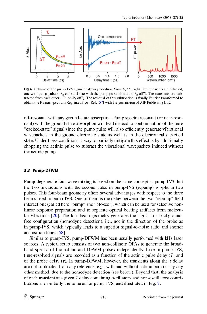
Fig. 6 Scheme of the pump-IVS signal analysis procedure. From left to right Two transients are detected,
one with pump pulse (“P 2 on”) and one with the pump pulse blocked (“P 2 off”). The transients are subtracted from each other (“P 2 on-P 2 off”). The residual of this subtraction is finally Fourier transformed to
obtain the Raman spectrum Reprinted from Ref. [57] with the permission of AIP Publishing LLC
218
Reprinted from the journal
1 3
off-resonant with any ground-state absorption. Pump spectra resonant (or near-resonant) with the ground-state absorption will lead instead to contamination of the pure
“excited-state” signal since the pump pulse will also efficiently generate vibrational
wavepackets in the ground electronic state as well as in the electronically excited
state. Under these conditions, a way to partially mitigate this effect is by additionally
chopping the actinic pulse to subtract the vibrational wavepackets induced without
the actinic pump.
3.3 Pump‑DFWM
Pump-degenerate four-wave mixing is based on the same concept as pump-IVS, but
the two interactions with the second pulse in pump-IVS (repump) is split in two
pulses. This four-beam geometry offers several advantages with respect to the three
beams used in pump-IVS. One of them is the delay between the two “repump” field
interactions (called here “pump” and “Stokes”), which can be used for selective nonlinear response preparation and to separate optical beating artifacts from molecular vibrations [20]. The four-beam geometry generates the signal in a backgroundfree configuration (homodyne detection), i.e., not in the direction of the probe as
in pump-IVS, which typically leads to a superior signal-to-noise ratio and shorter
acquisition times [58].
Similar to pump-IVS, pump-DFWM has been usually performed with kHz laser
sources. A typical setup consists of two non-collinear OPAs to generate the broadband spectra of the actinic and DFWM pulses independently. Like in pump-IVS,
time-resolved signals are recorded as a function of the actinic pulse delay (T) and
of the probe delay (τ). In pump-DFWM, however, the transients along the τ delay
are not subtracted from any reference, e.g., with and without actinic pump or by any
other method, due to the homodyne detection (see below). Beyond that, the analysis
of each transient at a given T delay containing oscillatory and non-oscillatory contributions is essentially the same as for pump-IVS, and illustrated in Fig. 7.
Fig. 6 Scheme of the pump-IVS signal analysis procedure. From left to right Two transients are detected,
one with pump pulse (“P 2 on”) and one with the pump pulse blocked (“P 2 off”). The transients are subtracted from each other (“P 2 on-P 2 off”). The residual of this subtraction is finally Fourier transformed to
obtain the Raman spectrum Reprinted from Ref. [57] with the permission of AIP Publishing LLC
218
Reprinted from the journal