

681
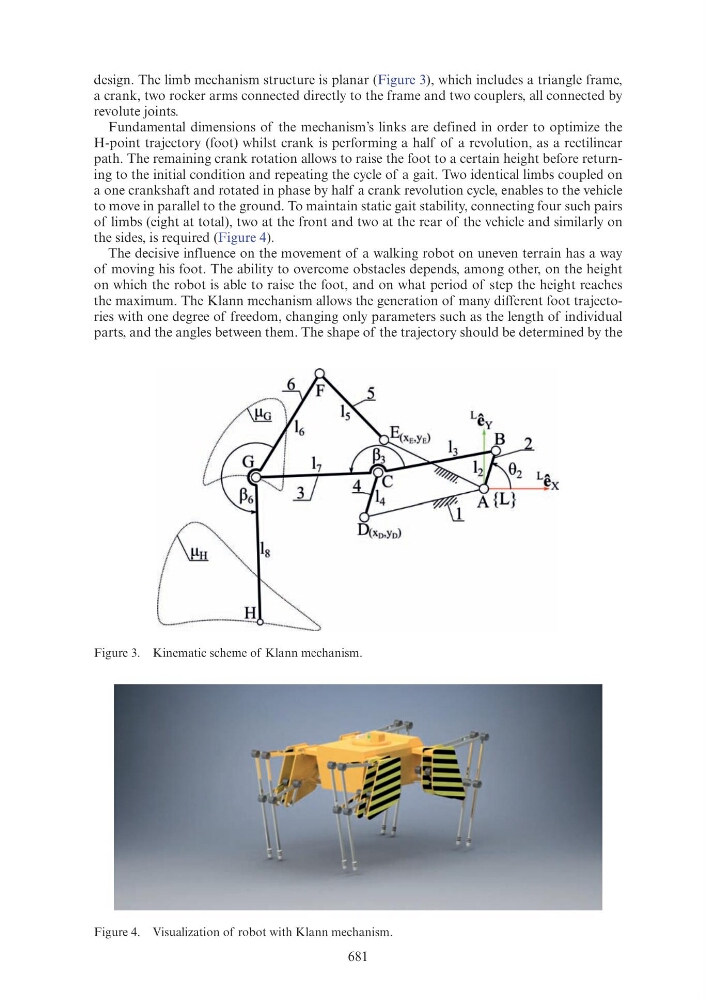
design. The limb mechanism structure is planar (Figure 3), which includes a triangle frame,
a crank, two rocker arms connected directly to the frame and two couplers, all connected by
revolute joints.
Fundamental dimensions of the mechanism’s links are defined in order to optimize the
H-point trajectory (foot) whilst crank is performing a half of a revolution, as a rectilinear
path. The remaining crank rotation allows to raise the foot to a certain height before returning to the initial condition and repeating the cycle of a gait. Two identical limbs coupled on
a one crankshaft and rotated in phase by half a crank revolution cycle, enables to the vehicle
to move in parallel to the ground. To maintain static gait stability, connecting four such pairs
of limbs (eight at total), two at the front and two at the rear of the vehicle and similarly on
the sides, is required (Figure 4).
The decisive influence on the movement of a walking robot on uneven terrain has a way
of moving his foot. The ability to overcome obstacles depends, among other, on the height
on which the robot is able to raise the foot, and on what period of step the height reaches
the maximum. The Klann mechanism allows the generation of many different foot trajectories with one degree of freedom, changing only parameters such as the length of individual
parts, and the angles between them. The shape of the trajectory should be determined by the
Figure 3. Kinematic scheme of Klann mechanism.
Figure 4. Visualization of robot with Klann mechanism.
2
< .·. · · H· · · · · · · · · · . . .
(~
··~·-······················· ·············