

667
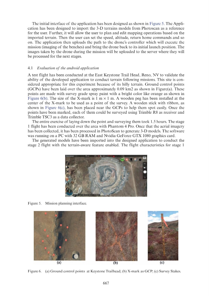
The initial interface of the application has been designed as shown in Figure 5. The Application has been designed to import the 3-D terrains models from Photoscan as a reference
for the user. Further, it will allow the user to plan and edit mapping operations based on the
imported terrain. Then the user can set the speed, altitude, return home commands and so
on. The application then uploads the path to the drone’s controller which will execute the
mission (imaging of the benches) and bring the drone back to its initial launch position. The
images taken by the drone during the mission will be uploaded to the server where they will
be processed for the next stages.
4.1 Evaluation of the android application
A test flight has been conducted at the East Keystone Trail Head, Reno, NV to validate the
ability of the developed application to conduct terrain following missions. This site is considered appropriate for this experiment because of its hilly terrain. Ground control points
(GCPs) have been laid over the area approximately 0.09 km2 as shown in Figure(a). These
points are made with survey grade spray paint with a bright color like orange as shown in
Figure 6(b). The size of the X-mark is 1 m × 1 m. A wooden peg has been installed at the
center of the X-mark to be used as a point of the survey. A wooden stick with ribbon, as
shown in Figure 6(c), has been placed near the GCPs to help them spot easily. Once the
points have been marked, each of them could be surveyed using Trimble R8 as receiver and
Trimble TSC3 as a data collector.
The entire exercise of laying down the point and surveying them took 1.5 hours. The stage
1 flight has been conducted over the area with Phantom 4 Pro. Once that the aerial imagery
has been collected, it has been processed in PhotoScan to generate 3-D models. The software
was running on a PC with 32 GB RAM and Nvidia GeForce GTX 1080 graphics card.
The generated models have been imported into the designed application to conduct the
stage 2 flight with the terrain-aware feature enabled. The flight characteristics for stage 1
Figure 5. Mission planning interface.
Figure 6. (a) Ground control points at Keystone Trailhead; (b) X-mark as GCP; (c) Survey Stakes.