

504
and the power of the main drive mechanism. The system also allows for the random influence
of belt and material wandering on idler loading.
The analyzed contact zones were compared with the zones analytically defined on the basis
of equations from (Gładysiewicz 2003):
• for the middle idler:
l
B
k
km
l
z
k
⋅
B
⋅
(
)
0 35 0
+ 02
2
,
,
35 0
+
(3)
• for the side idler:
l
B
k
ks
l
z
k
⋅
B
⋅
(
)
0 03 0
+ 16
2
,
,
03 0
+
(4)
where B = belt width; and k z = dimensionless belt loading coefficient.
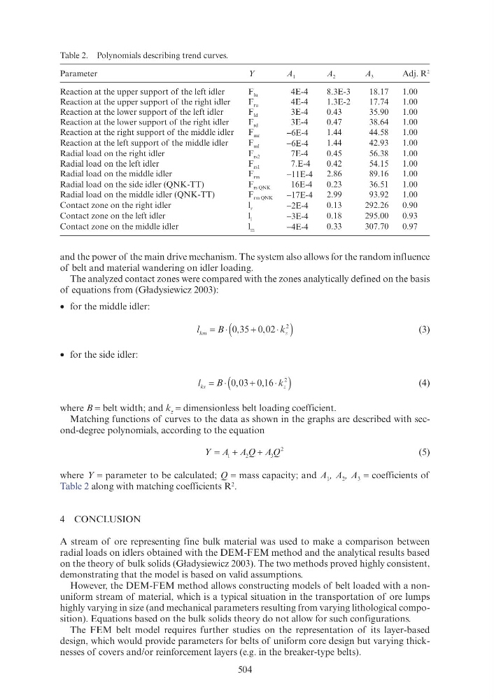
Matching functions of curves to the data as shown in the graphs are described with second-degree polynomials, according to the equation
A Q A Q
+
A
+
1
2
A A
+
A A
3
A A
2
(5)
where Y = parameter to be calculated; Q = mass capacity; and A 1 , A 2 , A 3 = coefficients of
Table 2 along with matching coefficients R
2
.
4 CONCLUSION
A stream of ore representing fine bulk material was used to make a comparison between
radial loads on idlers obtained with the DEM-FEM method and the analytical results based
on the theory of bulk solids (Gładysiewicz 2003). The two methods proved highly consistent,
demonstrating that the model is based on valid assumptions.
However, the DEM-FEM method allows constructing models of belt loaded with a nonuniform stream of material, which is a typical situation in the transportation of ore lumps
highly varying in size (and mechanical parameters resulting from varying lithological composition). Equations based on the bulk solids theory do not allow for such configurations.
The FEM belt model requires further studies on the representation of its layer-based
design, which would provide parameters for belts of uniform core design but varying thicknesses of covers and/or reinforcement layers (e.g. in the breaker-type belts).
Table 2. Polynomials describing trend curves.
Parameter
Y
A 1
A 2
A 3
Adj. R
2
Reaction at the upper support of the left idler
F lu
4E-4
8.3E-3
18.17
1.00
Reaction at the upper support of the right idler
F ru
4E-4
1.3E-2
17.74
1.00
Reaction at the lower support of the left idler
F ld
3E-4
0.43
35.90
1.00
Reaction at the lower support of the right idler
F rd
3E-4
0.47
38.64
1.00
Reaction at the right support of the middle idler
F mr
−6E-4
1.44
44.58
1.00
Reaction at the left support of the middle idler
F ml
−6E-4
1.44
42.93
1.00
Radial load on the right idler
F rs2
7E-4
0.45
56.38
1.00
Radial load on the left idler
F rs1
7.E-4
0.42
54.15
1.00
Radial load on the middle idler
F rm
−11E-4
2.86
89.16
1.00
Radial load on the side idler (QNK-TT)
F rs QNK
16E-4
0.23
36.51
1.00
Radial load on the middle idler (QNK-TT)
F rm QNK
−17E-4
2.99
93.92
1.00
Contact zone on the right idler
l r
−2E-4
0.13
292.26
0.90
Contact zone on the left idler
l l
−3E-4
0.18
295.00
0.93
Contact zone on the middle idler
l m
−4E-4
0.33
307.70
0.97