

190
Strain-Engineered MOSFETs
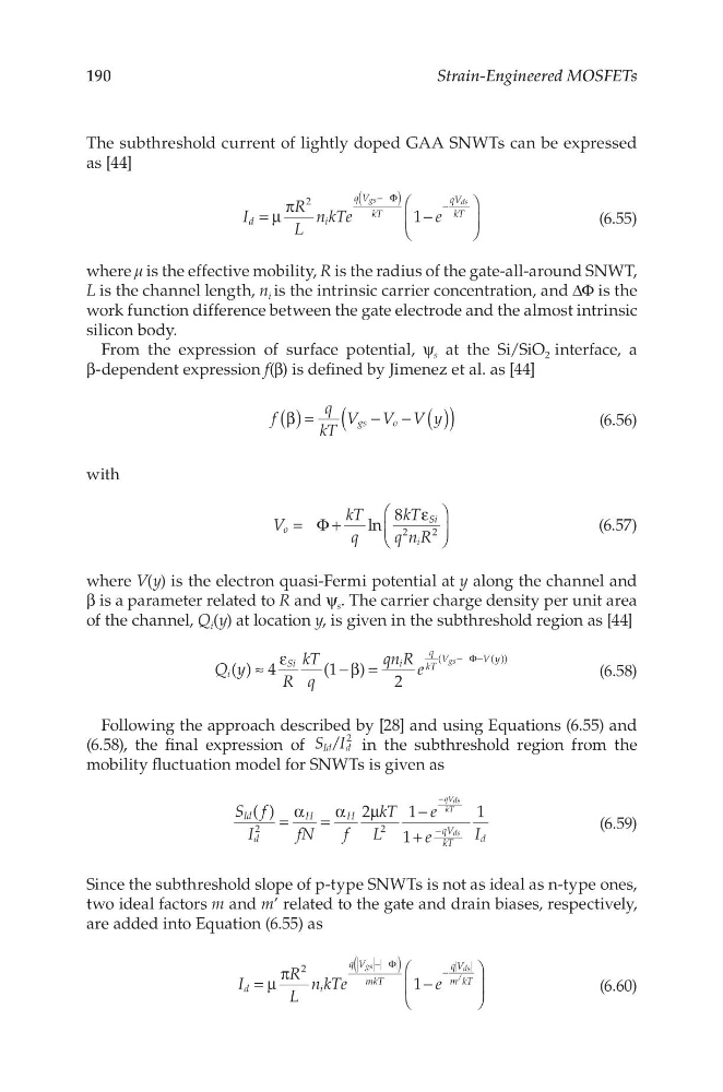
The subthreshold current of lightly doped GAA SNWTs can be expressed
as [44]
I
R
L
n kTe
e
1
d
i
q V
kT
qV
kT
2
gs
ds
= µ
π
−
(
)
− Φ
−
(6.55)
where μ is the effective mobility, R is the radius of the gate-all-around SNWT,
L is the channel length, n i is the intrinsic carrier concentration, and ΔΦ is the
work function difference between the gate electrode and the almost intrinsic
silicon body.
From the expression of surface potential, ψ s at the Si/SiO 2 interface, a
β-dependent expression f(β) is defined by Jimenez et al. as [44]
f
q
kT
V V V y
gs
o
(
)
( )
( )
β =
− −
(6.56)
with
V
kT
q
kT
q n R
ln
8
o
Si
i
2
2
= Φ+
ε
(6.57)
where V(y) is the electron quasi-Fermi potential at y along the channel and
β is a parameter related to R and ψ s . The carrier charge density per unit area
of the channel, Q i (y) at location y, is given in the subthreshold region as [44]
Q y
R
kT
q
qn R e
( ) 4
(1 )
2
i
Si
i
q
kT
V
Vy
(
())
gs
≈
ε
− β =
− Φ−
(6.58)
Following the approach described by [28] and using Equations (6.55) and
(6.58), the final expression of S I
/
Id d
2 in the subthreshold region from the
mobility fluctuation model for SNWTs is given as
S f
I
fN
f
kT
L
e
e
I
( )
2
1
1
1
Id
d
H
H
qV
kT
d
2
2
qVds
kT
ds
=
α =
α
µ
−
+
−
−
(6.59)
Since the subthreshold slope of p-type SNWTs is not as ideal as n-type ones,
two ideal factors m and m’ related to the gate and drain biases, respectively,
are added into Equation (6.55) as
I
R
L
n kTe
e
1
d
i
q V
mkT
qV
m kT
2
gs
ds
/
= µ
π
−
(
)
− Φ
−
(6.60)
Strain-Engineered MOSFETs
The subthreshold current of lightly doped GAA SNWTs can be expressed
as [44]
I
R
L
n kTe
e
1
d
i
q V
kT
qV
kT
2
gs
ds
= µ
π
−
(
)
− Φ
−
(6.55)
where μ is the effective mobility, R is the radius of the gate-all-around SNWT,
L is the channel length, n i is the intrinsic carrier concentration, and ΔΦ is the
work function difference between the gate electrode and the almost intrinsic
silicon body.
From the expression of surface potential, ψ s at the Si/SiO 2 interface, a
β-dependent expression f(β) is defined by Jimenez et al. as [44]
f
q
kT
V V V y
gs
o
(
)
( )
( )
β =
− −
(6.56)
with
V
kT
q
kT
q n R
ln
8
o
Si
i
2
2
= Φ+
ε
(6.57)
where V(y) is the electron quasi-Fermi potential at y along the channel and
β is a parameter related to R and ψ s . The carrier charge density per unit area
of the channel, Q i (y) at location y, is given in the subthreshold region as [44]
Q y
R
kT
q
qn R e
( ) 4
(1 )
2
i
Si
i
q
kT
V
Vy
(
())
gs
≈
ε
− β =
− Φ−
(6.58)
Following the approach described by [28] and using Equations (6.55) and
(6.58), the final expression of S I
/
Id d
2 in the subthreshold region from the
mobility fluctuation model for SNWTs is given as
S f
I
fN
f
kT
L
e
e
I
( )
2
1
1
1
Id
d
H
H
qV
kT
d
2
2
qVds
kT
ds
=
α =
α
µ
−
+
−
−
(6.59)
Since the subthreshold slope of p-type SNWTs is not as ideal as n-type ones,
two ideal factors m and m’ related to the gate and drain biases, respectively,
are added into Equation (6.55) as
I
R
L
n kTe
e
1
d
i
q V
mkT
qV
m kT
2
gs
ds
/
= µ
π
−
(
)
− Φ
−
(6.60)