

100
Strain-Engineered MOSFETs
2
ij
B
ξ are deformation potentials that correspond to the Bir and Pikus model,
and 4
2
i
B
ξ is a unitless constant that defines mainly a sign.
Using the stress tensor
σ from the input file, Sentaurus Device computes
from the stress coordinate system the tensor
′
σ in the crystal system using
Equation (4.4). The strain tensor
′
ε is a result of applying Hooke’s law in
Equation (4.2) to the stress. Using Equations (4.16) and (4.17), or Equation (4.18),
the energy band change can be computed for each conduction and valence
carrier subvalleys. The modifications of the band structure when silicon is
subjected to a stress have been discussed above. In the following section, we
discuss the mobility models developed and used in device simulation.
4.8 Piezoresistive Mobility Model
In this mobility modelling, two types of piezoresistance effects are considered.
One is the longitudinal piezoresistance coefficient ( )
||
π , when the current and
field are in the same direction of stress, and the other is transverse piezoresistance coefficient ( )
π ⊥ , when the current and field are perpendicular to stress.
( )
||
π and ( )
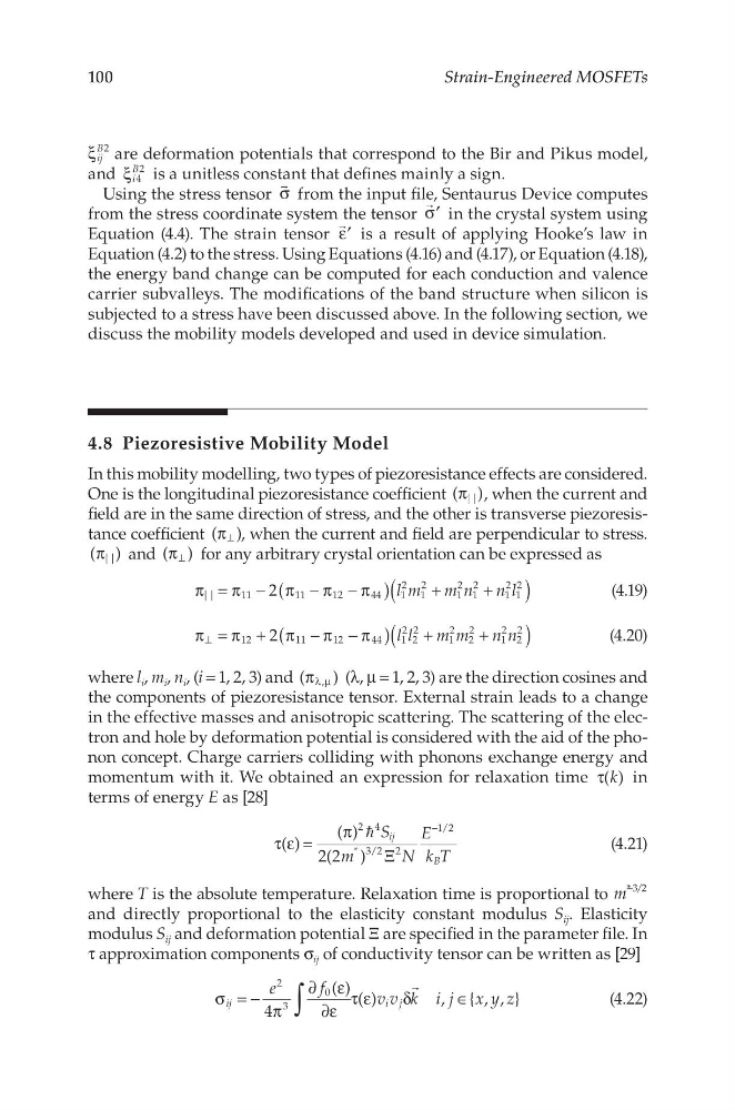
π ⊥ for any arbitrary crystal orientation can be expressed as
2
||
11
11
12
44
1
2
1
2
1
2
1
2
1
2
1
2
l m m n n l
(
)
(
)
π = π − π − π − π
+
+
(4.19)
2
12
11
12
44
1
2
2
2
1
2
2
2
1
2
2
2
l l m m n n
(
)
(
)
π = π + π − π − π
+
+
⊥
(4.20)
where l i , m i , n i , (i = 1, 2, 3) and (
)
,
π λ µ (λ, μ = 1, 2, 3) are the direction cosines and
the components of piezoresistance tensor. External strain leads to a change
in the effective masses and anisotropic scattering. The scattering of the electron and hole by deformation potential is considered with the aid of the phonon concept. Charge carriers colliding with phonons exchange energy and
momentum with it. We obtained an expression for relaxation time ( )
k
τ
in
terms of energy E as [28]
( )
( )
2(2 )
2 4
* 3/2 2
1/2
S
m
N
E
k T
ij
B
τ ε =
π
Ξ
−
(4.21)
where T is the absolute temperature. Relaxation time is proportional to
* 3/2
m
−
and directly proportional to the elasticity constant modulus S ij . Elasticity
modulus S ij and deformation potential Ξ are specified in the parameter file. In
τ approximation components σ ij of conductivity tensor can be written as [29]
4
( ) ( )
, { , , }
2
3
0
e
f
v v k i j x y z
ij
i j
∫
σ = − π
∂ ε
∂ε
τ ε
δ
∈
(4.22)
Strain-Engineered MOSFETs
2
ij
B
ξ are deformation potentials that correspond to the Bir and Pikus model,
and 4
2
i
B
ξ is a unitless constant that defines mainly a sign.
Using the stress tensor
σ from the input file, Sentaurus Device computes
from the stress coordinate system the tensor
′
σ in the crystal system using
Equation (4.4). The strain tensor
′
ε is a result of applying Hooke’s law in
Equation (4.2) to the stress. Using Equations (4.16) and (4.17), or Equation (4.18),
the energy band change can be computed for each conduction and valence
carrier subvalleys. The modifications of the band structure when silicon is
subjected to a stress have been discussed above. In the following section, we
discuss the mobility models developed and used in device simulation.
4.8 Piezoresistive Mobility Model
In this mobility modelling, two types of piezoresistance effects are considered.
One is the longitudinal piezoresistance coefficient ( )
||
π , when the current and
field are in the same direction of stress, and the other is transverse piezoresistance coefficient ( )
π ⊥ , when the current and field are perpendicular to stress.
( )
||
π and ( )
π ⊥ for any arbitrary crystal orientation can be expressed as
2
||
11
11
12
44
1
2
1
2
1
2
1
2
1
2
1
2
l m m n n l
(
)
(
)
π = π − π − π − π
+
+
(4.19)
2
12
11
12
44
1
2
2
2
1
2
2
2
1
2
2
2
l l m m n n
(
)
(
)
π = π + π − π − π
+
+
⊥
(4.20)
where l i , m i , n i , (i = 1, 2, 3) and (
)
,
π λ µ (λ, μ = 1, 2, 3) are the direction cosines and
the components of piezoresistance tensor. External strain leads to a change
in the effective masses and anisotropic scattering. The scattering of the electron and hole by deformation potential is considered with the aid of the phonon concept. Charge carriers colliding with phonons exchange energy and
momentum with it. We obtained an expression for relaxation time ( )
k
τ
in
terms of energy E as [28]
( )
( )
2(2 )
2 4
* 3/2 2
1/2
S
m
N
E
k T
ij
B
τ ε =
π
Ξ
−
(4.21)
where T is the absolute temperature. Relaxation time is proportional to
* 3/2
m
−
and directly proportional to the elasticity constant modulus S ij . Elasticity
modulus S ij and deformation potential Ξ are specified in the parameter file. In
τ approximation components σ ij of conductivity tensor can be written as [29]
4
( ) ( )
, { , , }
2
3
0
e
f
v v k i j x y z
ij
i j
∫
σ = − π
∂ ε
∂ε
τ ε
δ
∈
(4.22)