

Theor Chem Acc (2015) 134:117
1 3
dimers from the radial density topology of the monomers.
This is based on the linear alignment of a maximum in
radial density (charge accumulation) on one molecule with
a minimum or saddle in radial density (charge depletion)
for the other molecule. For example, the RX of one F 2
orients itself toward the line between the PSM and PM of
the other as illustrated in Fig. 8 . The same trend was also
found in Cl 2 . The predicted angles fall within one degree of
the computationally determined dimer angle in the lowest
energy dimer structure as shown in Table 6 .
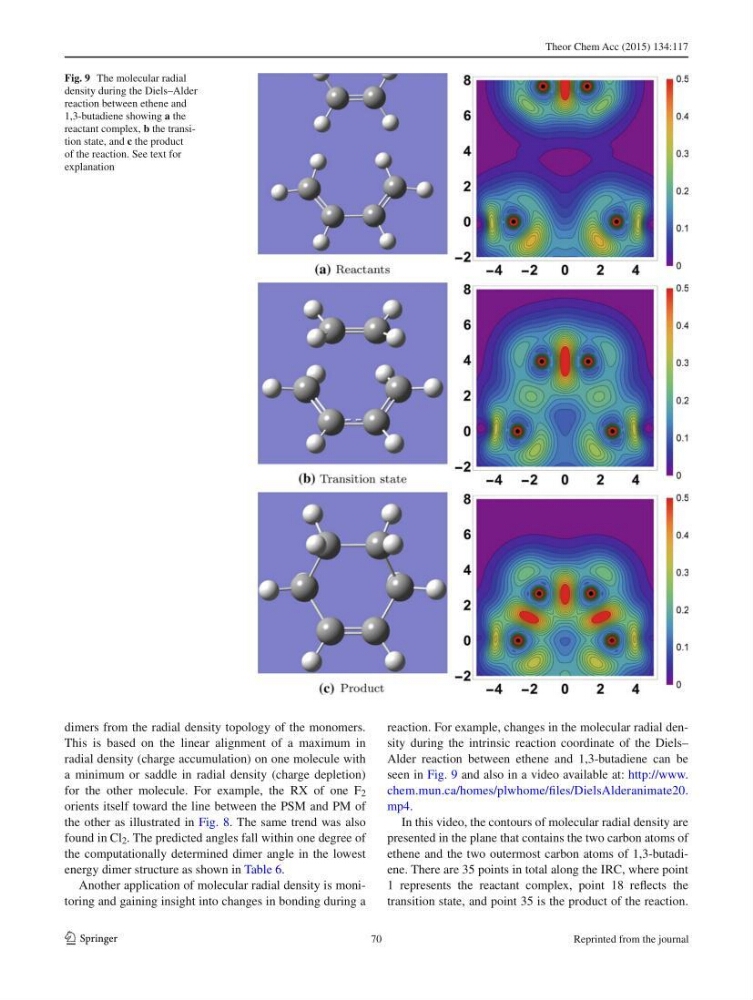
Another application of molecular radial density is monitoring and gaining insight into changes in bonding during a
reaction. For example, changes in the molecular radial density during the intrinsic reaction coordinate of the Diels–
Alder reaction between ethene and 1,3-butadiene can be
seen in Fig. 9 and also in a video available at: http://www.
chem.mun.ca/homes/plwhome/fi les/DielsAlderanimate20.
mp4 .
In this video, the contours of molecular radial density are
presented in the plane that contains the two carbon atoms of
ethene and the two outermost carbon atoms of 1,3-butadiene. There are 35 points in total along the IRC, where point
1 represents the reactant complex, point 18 refl ects the
transition state, and point 35 is the product of the reaction.
Fig. 9 The molecular radial
density during the Diels–Alder
reaction between ethene and
1,3-butadiene showing a the
reactant complex, b the transition state, and c the product
of the reaction. See text for
explanation
70
Reprinted from the journal
1 3
dimers from the radial density topology of the monomers.
This is based on the linear alignment of a maximum in
radial density (charge accumulation) on one molecule with
a minimum or saddle in radial density (charge depletion)
for the other molecule. For example, the RX of one F 2
orients itself toward the line between the PSM and PM of
the other as illustrated in Fig. 8 . The same trend was also
found in Cl 2 . The predicted angles fall within one degree of
the computationally determined dimer angle in the lowest
energy dimer structure as shown in Table 6 .
Another application of molecular radial density is monitoring and gaining insight into changes in bonding during a
reaction. For example, changes in the molecular radial density during the intrinsic reaction coordinate of the Diels–
Alder reaction between ethene and 1,3-butadiene can be
seen in Fig. 9 and also in a video available at: http://www.
chem.mun.ca/homes/plwhome/fi les/DielsAlderanimate20.
mp4 .
In this video, the contours of molecular radial density are
presented in the plane that contains the two carbon atoms of
ethene and the two outermost carbon atoms of 1,3-butadiene. There are 35 points in total along the IRC, where point
1 represents the reactant complex, point 18 refl ects the
transition state, and point 35 is the product of the reaction.
Fig. 9 The molecular radial
density during the Diels–Alder
reaction between ethene and
1,3-butadiene showing a the
reactant complex, b the transition state, and c the product
of the reaction. See text for
explanation
70
Reprinted from the journal