

Section and crossover should be designed to heat the oil to 920
F and retain it at
this temperature. The sections should be divided by a firebrick wall so that temperatures on both sides of the wall can be controlled independently by burner
adjustments.
Vendor may recommend that the convection side of the heater be used for
additional heater capacity or for steam generation or to remain unused if better
temperature control may result (Table 13).
Vessels
• T 301 Syn tower
$
Shell and heads
1,766,810
Trays
1,590,129
Internals
176,681
Total
3,533,620
• D 301 Reflux drum
$
Shell and heads
561,222
Lining
37,415
Internals
24,943
Total
623,580
Total vessel account = 4,157,200$
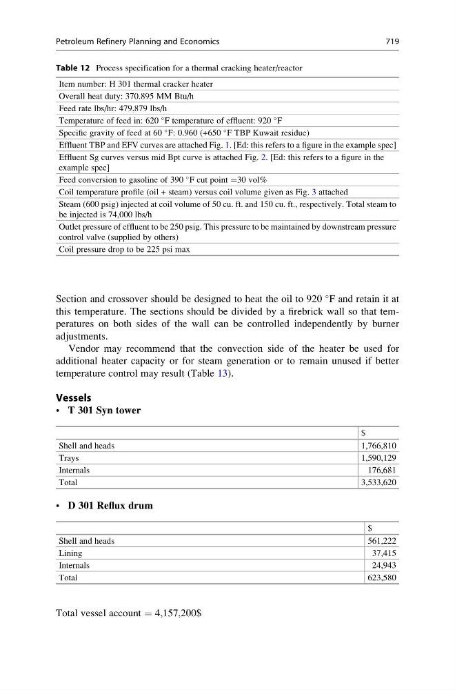
Table 12 Process specification for a thermal cracking heater/reactor
Item number: H 301 thermal cracker heater
Overall heat duty: 370.895 MM Btu/h
Feed rate lbs/hr: 479,879 lbs/h
Temperature of feed in: 620
F temperature of effluent: 920
F
Specific gravity of feed at 60
F: 0.960 (+650
F TBP Kuwait residue)
Effluent TBP and EFV curves are attached Fig. 1. [Ed: this refers to a figure in the example spec]
Effluent Sg curves versus mid Bpt curve is attached Fig. 2. [Ed: this refers to a figure in the
example spec]
Feed conversion to gasoline of 390
F cut point =30 vol%
Coil temperature profile (oil + steam) versus coil volume given as Fig. 3 attached
Steam (600 psig) injected at coil volume of 50 cu. ft. and 150 cu. ft., respectively. Total steam to
be injected is 74,000 lbs/h
Outlet pressure of effluent to be 250 psig. This pressure to be maintained by downstream pressure
control valve (supplied by others)
Coil pressure drop to be 225 psi max
Petroleum Refinery Planning and Economics
719