

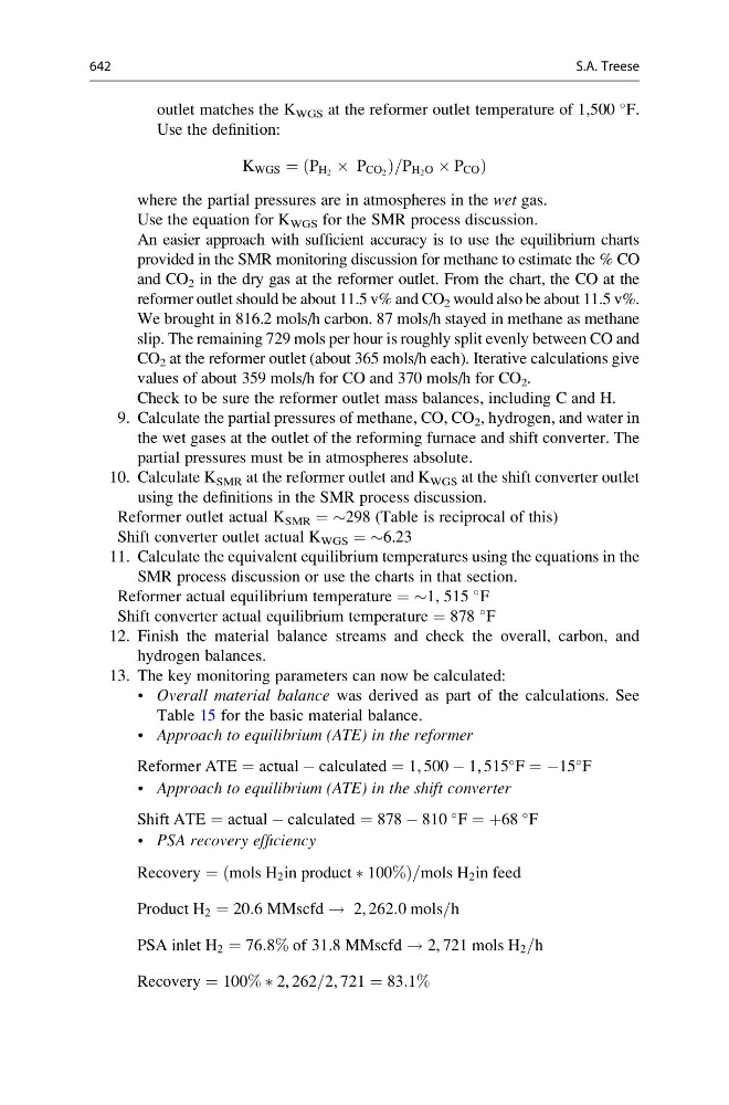
outlet matches the K WGS at the reformer outlet temperature of 1,500
F.
Use the definition:
K WGS ¼ P H 2 Â P CO 2
ð
Þ =P H 2 O Â P CO Þ
where the partial pressures are in atmospheres in the wet gas.
Use the equation for K WGS for the SMR process discussion.
An easier approach with sufficient accuracy is to use the equilibrium charts
provided in the SMR monitoring discussion for methane to estimate the % CO
and CO 2 in the dry gas at the reformer outlet. From the chart, the CO at the
reformer outlet should be about 11.5 v% and CO 2 would also be about 11.5 v%.
We brought in 816.2 mols/h carbon. 87 mols/h stayed in methane as methane
slip. The remaining 729 mols per hour is roughly split evenly between CO and
CO 2 at the reformer outlet (about 365 mols/h each). Iterative calculations give
values of about 359 mols/h for CO and 370 mols/h for CO 2 .
Check to be sure the reformer outlet mass balances, including C and H.
9. Calculate the partial pressures of methane, CO, CO 2 , hydrogen, and water in
the wet gases at the outlet of the reforming furnace and shift converter. The
partial pressures must be in atmospheres absolute.
10. Calculate K SMR at the reformer outlet and K WGS at the shift converter outlet
using the definitions in the SMR process discussion.
Reformer outlet actual K SMR = $298 (Table is reciprocal of this)
Shift converter outlet actual K WGS = $6.23
11. Calculate the equivalent equilibrium temperatures using the equations in the
SMR process discussion or use the charts in that section.
Reformer actual equilibrium temperature = $1, 515
F
Shift converter actual equilibrium temperature = 878
F
12. Finish the material balance streams and check the overall, carbon, and
hydrogen balances.
13. The key monitoring parameters can now be calculated:
• Overall material balance was derived as part of the calculations. See
Table 15 for the basic material balance.
• Approach to equilibrium (ATE) in the reformer
Reformer ATE ¼ actual À calculated ¼ 1, 500 À 1, 515
F ¼ À15
F
• Approach to equilibrium (ATE) in the shift converter
Shift ATE ¼ actual À calculated ¼ 878 À 810
F ¼ þ68
F
• PSA recovery efficiency
Recovery ¼ mols H 2 in product à 100%
ð
Þ =mols H 2 in feed
Product H 2 ¼ 20:6 MMscfd ! 2, 262:0 mols=h
PSA inlet H 2 ¼ 76:8% of 31:8 MMscfd ! 2, 721 mols H 2 =h
Recovery ¼ 100% Ã 2, 262=2, 721 ¼ 83:1%
642
S.A. Treese