

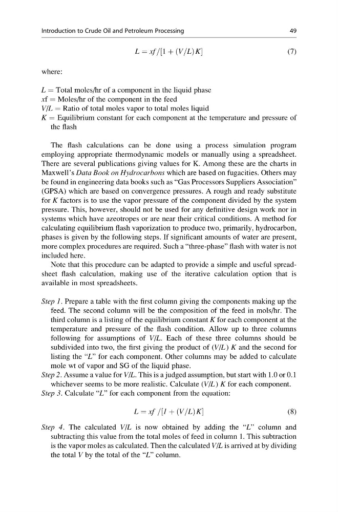
L ¼ xf = 1 þ V=L
ð
ÞK
½
(7)
where:
L = Total moles/hr of a component in the liquid phase
xf = Moles/hr of the component in the feed
V/L = Ratio of total moles vapor to total moles liquid
K = Equilibrium constant for each component at the temperature and pressure of
the flash
The flash calculations can be done using a process simulation program
employing appropriate thermodynamic models or manually using a spreadsheet.
There are several publications giving values for K. Among these are the charts in
Maxwell’s Data Book on Hydrocarbons which are based on fugacities. Others may
be found in engineering data books such as “Gas Processors Suppliers Association”
(GPSA) which are based on convergence pressures. A rough and ready substitute
for K factors is to use the vapor pressure of the component divided by the system
pressure. This, however, should not be used for any definitive design work nor in
systems which have azeotropes or are near their critical conditions. A method for
calculating equilibrium flash vaporization to produce two, primarily, hydrocarbon,
phases is given by the following steps. If significant amounts of water are present,
more complex procedures are required. Such a “three-phase” flash with water is not
included here.
Note that this procedure can be adapted to provide a simple and useful spreadsheet flash calculation, making use of the iterative calculation option that is
available in most spreadsheets.
Step 1. Prepare a table with the first column giving the components making up the
feed. The second column will be the composition of the feed in mols/hr. The
third column is a listing of the equilibrium constant K for each component at the
temperature and pressure of the flash condition. Allow up to three columns
following for assumptions of V/L. Each of these three columns should be
subdivided into two, the first giving the product of (V/L ) K and the second for
listing the “L” for each component. Other columns may be added to calculate
mole wt of vapor and SG of the liquid phase.
Step 2. Assume a value for V/L. This is a judged assumption, but start with 1.0 or 0.1
whichever seems to be more realistic. Calculate (V/L ) K for each component.
Step 3. Calculate “L” for each component from the equation:
L ¼ xf = 1 þ V=L
ð
ÞK
½
(8)
Step 4. The calculated V/L is now obtained by adding the “L” column and
subtracting this value from the total moles of feed in column 1. This subtraction
is the vapor moles as calculated. Then the calculated V/L is arrived at by dividing
the total V by the total of the “L” column.
Introduction to Crude Oil and Petroleum Processing
49
ð
ÞK
½
(7)
where:
L = Total moles/hr of a component in the liquid phase
xf = Moles/hr of the component in the feed
V/L = Ratio of total moles vapor to total moles liquid
K = Equilibrium constant for each component at the temperature and pressure of
the flash
The flash calculations can be done using a process simulation program
employing appropriate thermodynamic models or manually using a spreadsheet.
There are several publications giving values for K. Among these are the charts in
Maxwell’s Data Book on Hydrocarbons which are based on fugacities. Others may
be found in engineering data books such as “Gas Processors Suppliers Association”
(GPSA) which are based on convergence pressures. A rough and ready substitute
for K factors is to use the vapor pressure of the component divided by the system
pressure. This, however, should not be used for any definitive design work nor in
systems which have azeotropes or are near their critical conditions. A method for
calculating equilibrium flash vaporization to produce two, primarily, hydrocarbon,
phases is given by the following steps. If significant amounts of water are present,
more complex procedures are required. Such a “three-phase” flash with water is not
included here.
Note that this procedure can be adapted to provide a simple and useful spreadsheet flash calculation, making use of the iterative calculation option that is
available in most spreadsheets.
Step 1. Prepare a table with the first column giving the components making up the
feed. The second column will be the composition of the feed in mols/hr. The
third column is a listing of the equilibrium constant K for each component at the
temperature and pressure of the flash condition. Allow up to three columns
following for assumptions of V/L. Each of these three columns should be
subdivided into two, the first giving the product of (V/L ) K and the second for
listing the “L” for each component. Other columns may be added to calculate
mole wt of vapor and SG of the liquid phase.
Step 2. Assume a value for V/L. This is a judged assumption, but start with 1.0 or 0.1
whichever seems to be more realistic. Calculate (V/L ) K for each component.
Step 3. Calculate “L” for each component from the equation:
L ¼ xf = 1 þ V=L
ð
ÞK
½
(8)
Step 4. The calculated V/L is now obtained by adding the “L” column and
subtracting this value from the total moles of feed in column 1. This subtraction
is the vapor moles as calculated. Then the calculated V/L is arrived at by dividing
the total V by the total of the “L” column.
Introduction to Crude Oil and Petroleum Processing
49