

reforming, we have focused on gases through naphtha. There are several of that
type of plant in operation. The autothermal reformer feedstock has generally been
cleaned to SMR reformer standards, so sulfur in minimal.
For a POX unit, the feedstock generally still contains sulfur, ash, and other
contaminants. This has equipment, catalyst, and reliability implications.
Process: Step by Step
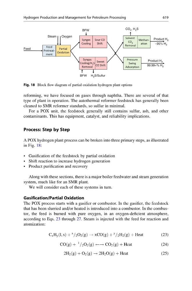
A POX hydrogen plant process can be broken into three primary steps, as illustrated
in Fig. 18:
• Gasification of the feedstock by partial oxidation
• Shift reaction to increase hydrogen generation
• Product purification and recovery
Along with these sections, there is a major boiler feedwater and steam generation
system, much like for an SMR plant.
We will consider each of these systems in turn.
Gasification/Partial Oxidation
The POX process starts with a gasifier or combustor. In the gasifier, the feedstock
that has been slurried and/or heated is introduced into a combustor. In the combustor, the feed is burned with pure oxygen, in an oxygen-deficient atmosphere,
according to Eqs. 23 through 27. Steam is injected with the feed for reaction and
atomization:
C x H y l, s
ð Þ þ
x
= 2 O 2 g
ð Þ ! xCO g
ð Þ þ
y
= 2 H 2 g
ð Þ þ Heat
(23)
CO g
ð Þ þ
1
= 2 O 2 g
ð Þ ! CO 2 g
ð Þ þ Heat
(24)
2H 2 g
ð Þ þ O 2 g
ð Þ ! 2H 2 O g
ð Þ þ Heat
(25)
BFW
CO 2 , H 2 S
Steam
Oxygen
Product H 2
~95% H 2
Feed
Product H 2
99.99+% H 2
BFW H 2 S/Sulfur
Feed
Pretreatment
Partial
Oxidation
Syngas
Cooling
Solvent
CO 2
Removal
Methanation
Syngas
Cooling/H 2 S
Removal
Sweet
CO Shift
Sour CO
Shift
Pressure
Swing
Adsorption
Fig. 18 Block flow diagram of partial oxidation hydrogen plant options
Hydrogen Production and Management for Petroleum Processing
619