

(or through) the steam generator using a damper system. Water supply to the
WHB is normally by thermosiphon from a steam drum located somewhat above
the WHB. Vaporization is typically 10–20 % in the WHB.
• Reforming furnace flue gas. One or more steam generation coils plus an economizer to preheat boiler feedwater are normally included in the flue gas ducting.
These are usually thermosiphon or forced circulation steam generators tied to the
main steam drum.
• High-temperature shift reactor effluent. Many plants employ a separate steam
generator(s), sometimes kettle style, on the shift reactor effluent to recover
100
Pressure, psig
200
600
300
400
500
Temperature, °F
1
10
Equilibrium % CO in Dry Gas
700
2
3
4
5
6
7
8
9
20
Steam/Carbon Ratio
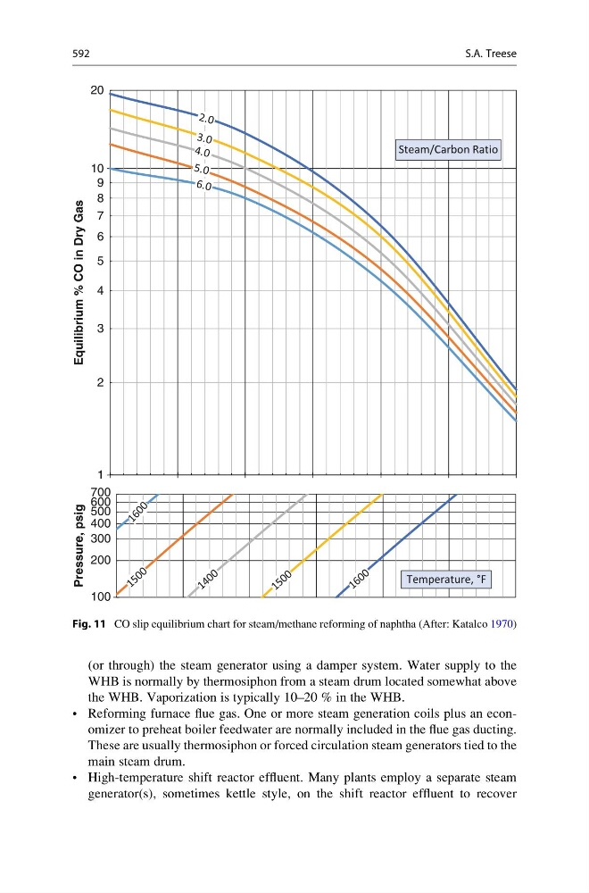
Fig. 11 CO slip equilibrium chart for steam/methane reforming of naphtha (After: Katalco 1970)
592
S.A. Treese